Screwdriver head turning-milling combined machine

A screwdriver head and compound machine technology, applied in the direction of metal processing machinery parts, other manufacturing equipment/tools, large fixed members, etc., can solve the problems of reduced processing accuracy, processing efficiency, and high processing cost, and achieve fast processing speed and processing accuracy High, space-saving and processing cost-effective

Active Publication Date: 2014-07-23
美事满工具(海安)有限公司
View PDF7 Cites 12 Cited by
  • Summary
  • Abstract
  • Description
  • Claims
  • Application Information

AI Technical Summary

Problems solved by technology

[0002] The raw material of the screwdriver head can only be processed into a screwdriver head through multiple processes of turning and milling. At present, the processing of the screwdriver head is to install it on the milling machine for processing, and then put it on the lathe for processing. Second positioning reduces the processing accuracy and processing efficiency, requires multiple machine tools, and the processing cost is high

Method used


Image

  • Screwdriver head turning-milling combined machine
  • Screwdriver head turning-milling combined machine
  • Screwdriver head turning-milling combined machine

Examples


Embodiment

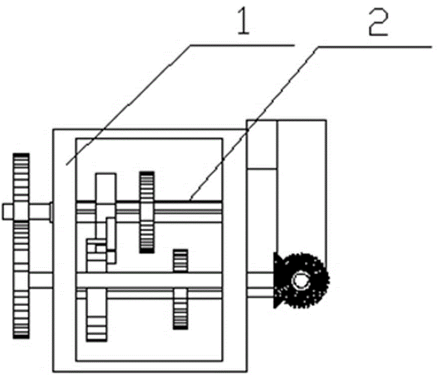
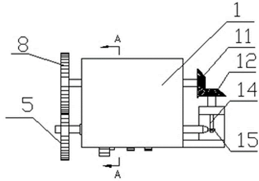
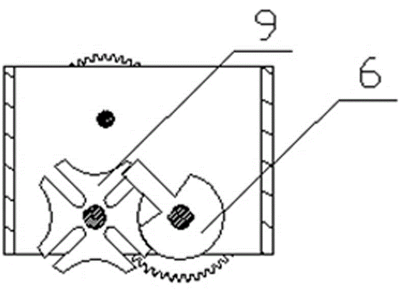
[0019] Embodiment: A screwdriver head turning and milling compound machine, including a spindle box 1, a driving shaft 2, a driven shaft 3, a turning and milling spindle 4, a first driving meshing wheel 5, a second driving meshing wheel 6, and a third driving meshing wheel 7. The first driven meshing wheel 8, the second driven meshing wheel 9, the third driven meshing wheel 10, the first bevel gear 11, the second bevel gear 12, the knife rest 13 and the power output device, the drive shaft 2. The driven shaft 3 and the turning-milling spindle 4 can be rotated and positioned in parallel in the headstock 1. The power output device drives the driving shaft 2 to rotate. The first driving meshing wheel 5 is fixed on one end of the driving shaft 2. The first driven meshing wheel 8 is fixed on one end of the driven shaft 3, and the first driving meshing wheel 5 is meshed with the first driven meshing wheel 8 for transmission, the second and third driving meshing wheels can be synchron...


PUM


Abstract

The invention discloses a screwdriver head turning-milling combined machine. A driving shaft, a driven shaft and a turning-milling main shaft are positioned in parallel in a main shaft box in a rotating mode, the driving shaft is driven by a power output device, a first driving meshing gear at one end of the driving shaft and a first driven meshing gear at one end of the driven shaft are meshed for transmission, a second driving meshing gear and a third driving meshing gear can be synchronously and axially positioned on the driving shaft in a sliding mode and can be meshed with a second driven meshing gear and a third driven meshing gear which are fixed to the two ends of the turning-milling main shaft respectively to form a first transmission pair and a second transmission pair, and the first transmission pair and the second transmission pair can be alternatively meshed for transmission; the other end of the driven shaft and a second bevel gear on a tool rest are meshed for transmission through a first bevel gear, the second bevel gear is coaxially and fixedly connected with an installation shaft for installing a turning tool and a milling tool, and the other end of the turning-milling main shaft is provided with a screwdriver head clamping device corresponding to the turning tool and the milling tool. A screwdriver head can be turned and milled through one-off clamping, machining accuracy and machining speed are high, and space occupied by machining equipment and machining cost are saved.

Description

technical field [0001] The invention relates to a screwdriver head processing device, in particular to a screwdriver head turning and milling compound machine. Background technique [0002] The raw material of the screwdriver head can only be processed into a screwdriver head through multiple processes of turning and milling. At present, the processing of the screwdriver head is to install it on the milling machine for processing, and then put it on the lathe for processing. Multiple positioning reduces the machining accuracy and efficiency, requires multiple machine tools, and the processing cost is high. Contents of the invention [0003] In order to overcome the above-mentioned defects, the present invention provides a screwdriver bit turning-milling compound machine, which can quickly realize turning and milling replacement, and realize fast and high-precision machining and forming of the screwdriver bit. [0004] In order to solve the technical problems, the present ...

Claims


Application Information

Patent Timeline
Patent Type & Authority Applications(China)
IPC IPC(8): B23P23/00B23Q5/10B23Q5/16
CPCB23P23/02B23Q1/70B23Q5/12B23Q2705/06
Inventor 黄国庆洪志彬
Owner 美事满工具(海安)有限公司
Why Eureka
Try Eureka