Bottom rotating and high-vibration grinding device

A technology with high rotation and external rotation, which is applied in the direction of grinding/polishing safety devices, grinding heads, grinding racks, etc., and can solve problems such as damage to the grinding surface, waste of sandpaper, uncontrollable vibration frequency and speed, etc.

Inactive Publication Date: 2016-11-09
东莞市春草研磨科技有限公司
View PDF10 Cites 0 Cited by
  • Summary
  • Abstract
  • Description
  • Claims
  • Application Information

AI Technical Summary

Problems solved by technology

However, when single-point constant pressure grinding is required in the field of automation, the non-rotational vibration type cannot evenly act on the entire piece of sandpaper during single-point grinding, resulting in waste of sandpaper.
However, the high-rotation eccentric vibration type will cause rotating cutting force due to high rotation during grinding, which will damage the polished surface; and because their power source is high-pressure gas or induction motor (without speed regulation), the vibration frequency and speed cannot be controlled.

Method used


Image

  • Bottom rotating and high-vibration grinding device
  • Bottom rotating and high-vibration grinding device
  • Bottom rotating and high-vibration grinding device

Examples


Embodiment Construction

[0018] The present application will be described in further detail below in conjunction with the accompanying drawings and specific embodiments. It should be understood that the following exemplary embodiments and descriptions are only used to explain the present invention, not as a limitation to the present invention, and, in the case of no conflict, the embodiments in the present invention and the features in the embodiments can be combined with each other .

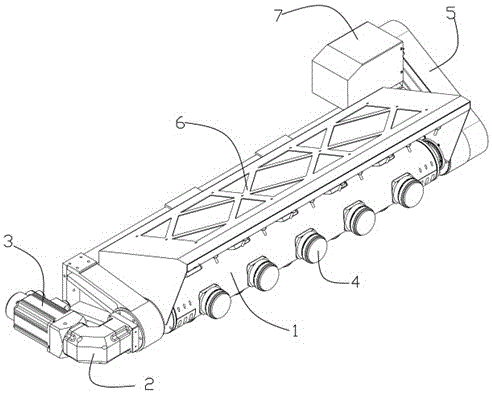
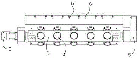
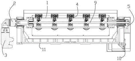
[0019] Such as Figure 1~Figure 5 As shown, the present invention provides a grinding device with bottom rotation and high vibration. One end of the outer transverse shaft 1 and an outer rotating power mechanism that provides rotational power for the outer transverse shaft 1, an active power mechanism installed on the other end of the outer transverse shaft 1 and connected to the inner main shaft 9, and a control module for controlling the operation of the device; the device also A grinding module 4 passing through t...


PUM


Abstract

The invention relates to a bottom rotating and high-vibration grinding device, which comprises an outer transverse shaft, an inner main shaft, an outer rotating power mechanism, a main power mechanism and a control module, wherein the outer transverse shaft is provided with an outer transverse shaft cavity; the inner main shaft is coaxial with the outer transverse shaft and is positioned inside the outer transverse shaft cavity; the outer rotating power mechanism is arranged at one end of the outer transverse shaft and provides rotating power for the outer transverse shaft; the main power mechanism is arranged at the other end of the outer transverse shaft and is connected with the inner main shaft; the control module controls the device to operate; the bottom rotating and high-vibration grinding device is also provided with a grinding module passing through the outer transverse shaft to be connected with the inner main shaft. Through the effective combination of inner and outer high-speed rotation and coaxial positioning of the outer transverse shaft and the inner main shaft, different rotation requirements of the inner main shaft and the outer transverse shaft are realized; the mutual interference is avoided; output power is provided for one group or a plurality of groups of grinding modules through the main inner shaft; the high-speed rotation of a plurality of groups of grinding heads can be realized; during the grinding, the goal of controlling the vibration frequency and the speed can be achieved through regulating the main power motor and the outer rotating power mechanism.

Description

technical field [0001] The invention relates to the technical field of grinding and polishing, in particular to a grinding device with bottom rotation and high vibration. Background technique [0002] At present, the grinding head in the surface grinding industry is mainly dominated by two types: no rotation vibration and high rotation eccentric vibration. However, when single-point constant pressure grinding is required in the field of automation, the non-rotational vibration type cannot evenly act on the entire piece of sandpaper during single-point grinding, resulting in waste of sandpaper. However, the high-rotation eccentric vibration type causes high-rotation cutting force during grinding and damages the polished surface; and because their power source is high-pressure gas or induction motor (without speed regulation), the vibration frequency and speed cannot be controlled. Contents of the invention [0003] The technical problem to be solved by the present inventio...

Claims


Application Information

Patent Timeline
Patent Type & Authority Applications(China)
IPC IPC(8): B24B41/047B24B41/02B24B55/04B24B55/06
CPCB24B41/0475B24B41/02B24B55/04B24B55/06
Inventor 吴三桂黄大路王平李双羊张丙庚孟力
Owner 东莞市春草研磨科技有限公司
Why Eureka
Try Eureka