Computer imaging type direct plate making equipment and plate making method

A computer and equipment technology, applied in the field of computer imaging direct plate-making equipment and plate-making, can solve problems such as LED light-emitting units cannot emit light normally, LED arrays cannot be used normally, blurred exposure graphic edges, etc., to achieve large-area one-time exposure, improve Effects of long plate-making cycle and ablation instability, reduced number of image transfers

Active Publication Date: 2014-07-30
青岛斯博锐意电子技术有限公司
View PDF8 Cites 9 Cited by
  • Summary
  • Abstract
  • Description
  • Claims
  • Application Information

AI Technical Summary

Problems solved by technology

However, this technology has the following disadvantages: 1. The accuracy is not high. As we all know, LED lights are point light sources, and the array formed by LED lights is formed by a series of LED light-emitting units arranged at intervals. The light emitted by a single LED light is not a completely parallel beam. There is also scattered light in the interval between LED lamps, and the light of a single LED lamp spreads in the form of strong center and weak edge, especially when the distance between the LED lamp and the printing plate is large, the light of the LED lamp located at the edge of the image shines on the Halos are formed on the printing plate, which leads to blurred edges of the exposure pattern, resulting in a decrease in imaging accuracy; 2. High cost, LED arrays, especially UVLED lamps, usually use special semiconductor materials, and the semiconductor materials are processed by the overall photolithography of the wafer , usually grown by CVD method, the cost is extremely high; 3. Poor fault tolerance, easy to form bad spots in the LED array due to factors such as production and maintenance, that is, individual LED light-emitting units cannot emit light normally, and due to process limitations, it is difficult to replace individual LED particles , so that the whole LED array cannot be used normally
[0014] It can be seen that in the prior art, especially in the widely used CTP and CTcP plate-making processes, there are insurmountable technical obstacles in the existing technical level and solution ideas. Due to technical problems such as high cost, short equipment life cycle and high cost of consumables, it is urgent to change the design idea and provide a new generation of computer plate-making equipment with simple structure, easy maintenance and low plate-making cost

Method used


Image

  • Computer imaging type direct plate making equipment and plate making method
  • Computer imaging type direct plate making equipment and plate making method
  • Computer imaging type direct plate making equipment and plate making method

Examples


Embodiment Construction

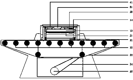
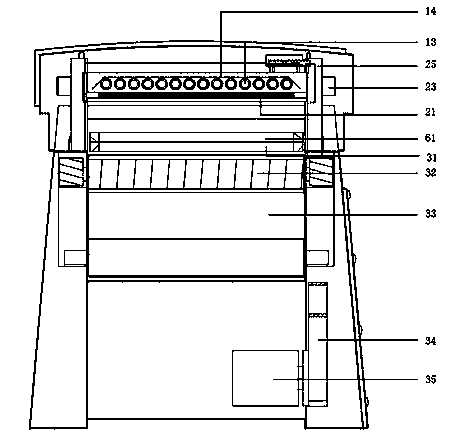
[0038] In order to make the technical scheme of the present invention and its technical effects clearer and clearer, the following combination figure 1 -6 The specific embodiment of the present invention is described in further detail. It should be understood that the following specific embodiments are only used to explain the present invention, and are not intended to limit the present invention.

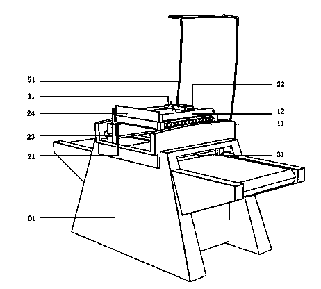
[0039] like figure 1 As shown, it is a front perspective view of a computer imaging to plate making apparatus in a specific embodiment. The computer imaging to plate making equipment 01 includes: an exposure device 11 , a printing image forming device 21 , a printing plate carrying device 31 , and a timing control device 41 . From the perspective of the overall structure, the exposure light source 11, the printing image imaging device 21, and the printing plate carrying device 31 are arranged coaxially in sequence, mainly to ensure the high efficiency and accuracy of the exposure...


PUM

PropertyMeasurementUnit
wavelengthaaaaaaaaaa

Abstract

The invention provides computer imaging type direct plate making equipment and a plate making method. The equipment comprises an exposure light source, a print image imaging device and a printing plate carrying device, which are arranged coaxially; the exposure light source is used for irradiating light to cure a photosensitive material loaded on a printing plate; the print image imaging device is used for forming a target image to replace a film, so as to mask the light from the exposure light source, and thus a corresponding exposure image is formed on the printing plate; to improve the exposure efficiency and the plate making efficiency, the print image imaging device is provided with a light guide layer for trimming non-uniform exposure light to uniform parallel light. Due to the introduction of a light homogenizing layer, dependence on a light source is further reduced, and in particular, good plate making precision can be obtained by combination of light sources with different specifications, light sources or spot light sources with different surface luminescence uniformity and line light sources. A plate making process formed by the plate making equipment can adapt to the plate making requirements of high precision and low cost.

Description

technical field [0001] The invention belongs to the field of printing plate making, and in particular relates to a computer imaging direct plate making device and a plate making method. Background technique [0002] The plate-making process is an important step in the pre-press process. It plays an important role in the entire printing process and has an extremely important impact on the color, tone and registration of printed matter. With the development of science and technology, the plate making process is also constantly evolving, from traditional film plate making to wax spray plate making, inkjet plate making, and now widely used laser plate making, etc., with the development of computer technology, plate making process gradually and Combined, and continue to develop toward the direction of high efficiency, environmental protection, and low cost, thus forming the computer-to-plate technology. [0003] The so-called computer to plate (Computer to Plate, referred to as ...

Claims


Application Information

Patent Timeline
Patent Type & Authority Applications(China)
IPC IPC(8): G03F7/00B41C1/00
Inventor 杨涛
Owner 青岛斯博锐意电子技术有限公司
Why Eureka
Try Eureka