
Transformer Winding Loose Fault Detection Method Based on Average Displacement Method
A transformer winding, average displacement technology, applied in instruments, measuring devices, measuring ultrasonic/sonic/infrasonic waves, etc.
- Summary
- Abstract
- Description
- Claims
- Application Information
AI Technical Summary
Problems solved by technology
Method used
Image

Examples
Embodiment 1
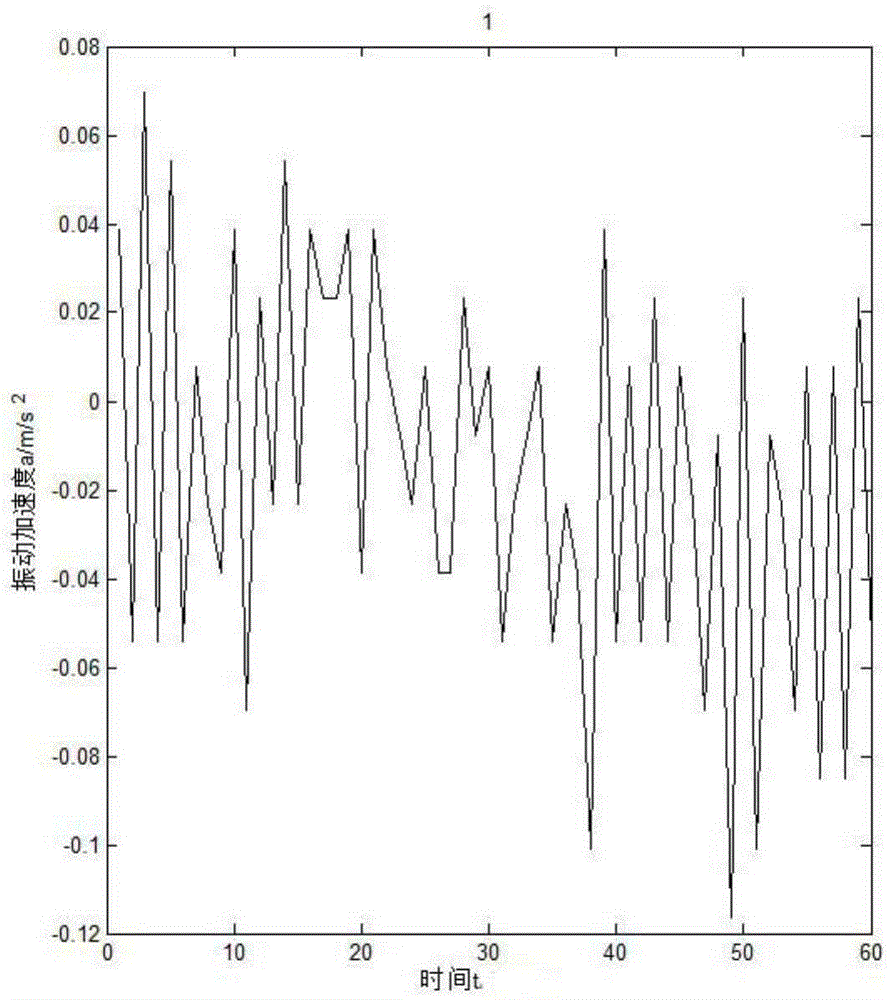
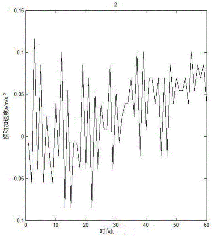
[0041] In this embodiment, a power transformer produced by Jiangsu Hongyuan Electric Co., Ltd. (the model of the transformer is S9-M-100 / 10) is set for loose winding faults, and fault detection is performed. The parameters of the transformer are shown in Table 1. Show.
[0042] Table 1
[0043] model
join group
voltage ratio
S9-M-100 / 10
Yyn0
10 / 0.4kV
High side I N
Low side I N
Short circuit impedance
5.77A
144.3A
3.98%
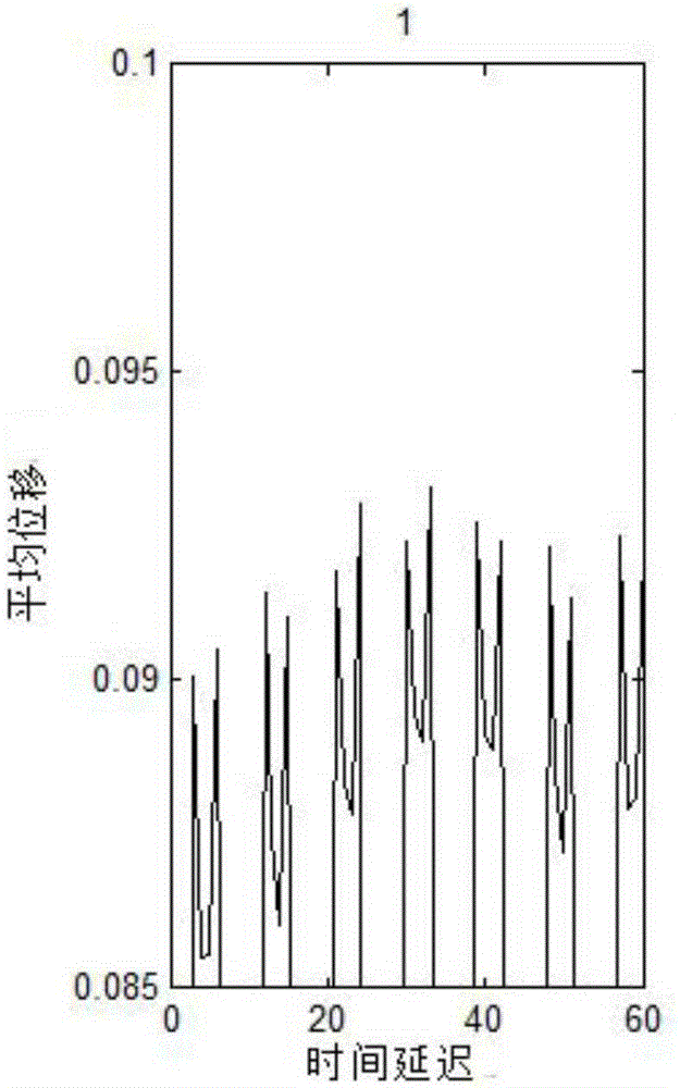
[0044] The short-circuit test method used in this embodiment is: short-circuit the three-phase windings on the low-voltage side of the experimental transformer, adjust the applied voltage through a voltage regulator on the high-voltage side, so that the short-circuit current on the low-voltage side is close to the rated current, that is, 140A, and simulate the high current of the transformer during rated operation. When the short-circuit current reaches the rated current, the vibration ...
Embodiment 2
[0062] This embodiment is basically the same as the first embodiment, the difference lies in the selection of j value.
[0063] What needs to be explained here is that the selection of the value of j in this embodiment is very important, and the value should be as large as possible in a meaningful situation, and when the calculation time delay is When the average displacement value between the values is small, it is easy to cause large errors due to the small number of vibration data samples involved in the calculation; if it is too small, it cannot reflect the repeatability and regularity of the evaluation factor △s well. Therefore, usually the optimal value of j should be ,in is not greater than The largest integer of , for example, it is best when j is 3999 in this embodiment.
[0064] When j is 3999, according to past experience, the value of the warning threshold in this embodiment is 1.25×10 -3 j≈5, the fault threshold value is 3.01×10 -3 j≈12.
[0065] Adopt...
PUM
 Abstract
Description
Claims
Application Information