Two-end constant current device

A technology of constant current devices and depletion transistors, which is applied in the direction of instruments, electrical variable adjustment, control/regulation systems, etc., can solve the problems of poor temperature stability, narrow constant current area, and low breakdown voltage, and achieve temperature stability High, fast response, high breakdown voltage effect

Active Publication Date: 2014-09-17
GPOWER SEMICON
View PDF10 Cites 16 Cited by
  • Summary
  • Abstract
  • Description
  • Claims
  • Application Information

AI Technical Summary

Problems solved by technology

[0004] In view of this, an embodiment of the present invention provides a two-terminal constant current device to solve the problems of slow response speed, low breakdown voltage, narrow constant current region, poor temperature stability and low temperature resistance of current two-terminal constant current devices.

Method used


Image

  • Two-end constant current device
  • Two-end constant current device
  • Two-end constant current device

Examples


Embodiment 1

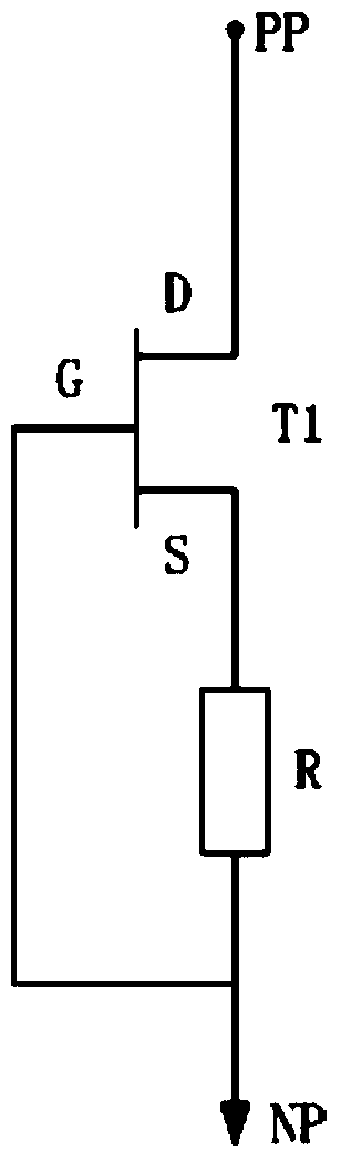
[0028] figure 1 It is a schematic diagram of a two-terminal constant current device provided in Embodiment 1 of the present invention, see figure 1 . The two-terminal constant current device includes: a first N-type depletion transistor T1 and a resistor R, wherein the source of the first N-type depletion transistor is connected to the first end of the resistor R, and the first The gate of an N-type depletion transistor T1 is connected to the second end of the resistor R, wherein the first N-type depletion transistor T1 is a gallium nitride depletion transistor, and the resistor R is separated resistor or a resistor integrated with the first N-depletion transistor T1.

[0029] In this embodiment, the two-terminal constant current device further includes a first-type electrode and a second-type electrode. Wherein, the first-type electrode is the anode PP of the two-terminal constant current device, the drain of the first N-type depletion transistor T1 is used as the anode PP...

Embodiment 2

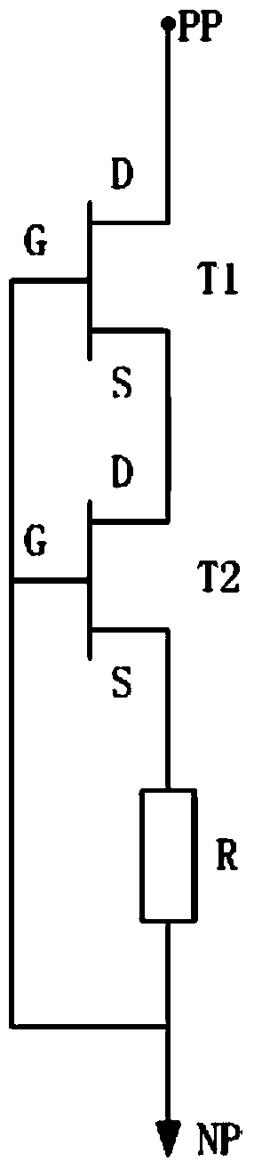
[0044] image 3 It is a schematic diagram of a two-terminal constant current device provided in Embodiment 2 of the present invention. This embodiment is based on Embodiment 1, see image 3 , the two-terminal constant current device includes a first N-type depletion transistor T1, a second N-type depletion transistor T2 and a resistor R, wherein the drain of the second N-type depletion transistor T2 is connected to the The source of the first N-type depletion transistor T1 is connected, the source of the second N-type depletion transistor T2 is connected to the first end of the resistor R, and the second N-type depletion transistor T2 The gate of the gate is connected to the gate of the first N-type depletion transistor T1 and then connected to the second end of the resistor R. Wherein, the first N-type depletion transistor T1 and the second N-type depletion transistor T2 are gallium nitride depletion transistors, and the resistor R is a separate resistor or connected with t...

Embodiment 3

[0054] Figure 4 It is a schematic diagram of a two-terminal constant current device provided by Embodiment 3 of the present invention. This embodiment is based on the above-mentioned embodiment, see Figure 4 , the two-terminal constant current device includes a first N-type depletion transistor T1, a second N-type depletion transistor T2 and a resistor R. Wherein, the second N-type depletion transistor T2 is composed of N third N-type depletion transistors T3. The third N-type depletion transistor T3 is a gallium nitride depletion transistor, wherein N is an integer greater than or equal to 2.

[0055] The gates of the N third N-type depletion transistors T3 are connected together as the gates of the second N-type depletion transistor T2, and the gates of the first third N-type depletion transistor T31 The drain serves as the drain of the second N-type depletion transistor T2, and the drain of each third N-type depletion transistor T3 is connected to the source of the pre...


PUM


Abstract

The invention discloses a two-end constant current device, comprising a first depletion type transistor and a resistor, wherein the source electrode of the first depletion type transistor is connected with a first end of the resistor, the grid electrode of the first depletion type transistor is connected with a second end of the resistor, and the first depletion type transistor is a gallium nitride depletion type transistor. The constant current effect of the two-end constant current device is realized by the negative feedback effect of the resistor, and the two-end constant current device has the advantages of high response speed, high breakdown voltage, high temperature resistance, good constant-current characteristic and high temperature stability by using the gallium nitride transistor characteristics of being high in response speed, being capable of bearing higher withstand voltage and being affected slightly by temperature.

Description

technical field [0001] The invention relates to the technical field of semiconductors, in particular to a two-terminal constant current device. Background technique [0002] A two-terminal constant current device is a device that provides a stable current when the voltage changes, which is equivalent to a constant current source or a current limiting circuit for the maximum peak current. Even if the voltage is unstable or the load resistance changes greatly, it can guarantee The supply current is stable. [0003] The constant current source composed of constant current devices has the advantages of simple structure, good constant current characteristics and convenient use, which makes the constant current devices have a wide range of applications. In the prior art, commonly used semiconductor constant current devices are devices based on bipolar transistors or field effect transistors. Among them, devices based on field effect transistors have the advantages of low noise an...

Claims


Application Information

Patent Timeline
Patent Type & Authority Applications(China)
IPC IPC(8): G05F1/56
Inventor 李元
Owner GPOWER SEMICON
Why Eureka
Try Eureka