Display system

A display system and display chip technology, applied in the field of optical instruments, can solve the problems of not having image content transmitted into the human eye and hindering the popularization and application of head-mounted visual equipment, so as to achieve easy market promotion and low investment cost Effect

Active Publication Date: 2014-09-24
BEIJING LLVISION TECH CO LTD
View PDF10 Cites 7 Cited by
  • Summary
  • Abstract
  • Description
  • Claims
  • Application Information

AI Technical Summary

Problems solved by technology

However, at present, the head-mounted visual devices of Google, Epson, and Sony do not have the function of sharing the image content transmitted into the human eye with other people at the same time
This problem hinders the promotion and application of compact display systems such as head-mounted video devices in the market

Method used


Image

  • Display system
  • Display system
  • Display system

Examples


Embodiment Construction

[0031] The following will clearly and completely describe the technical solutions in the embodiments of the present invention with reference to the drawings in the embodiments of the present invention. Apparently, the described embodiments are only some of the embodiments of the present invention, but not all of them. Based on the embodiments of the present invention, all other embodiments obtained by persons of ordinary skill in the art without making creative efforts belong to the protection scope of the present invention.

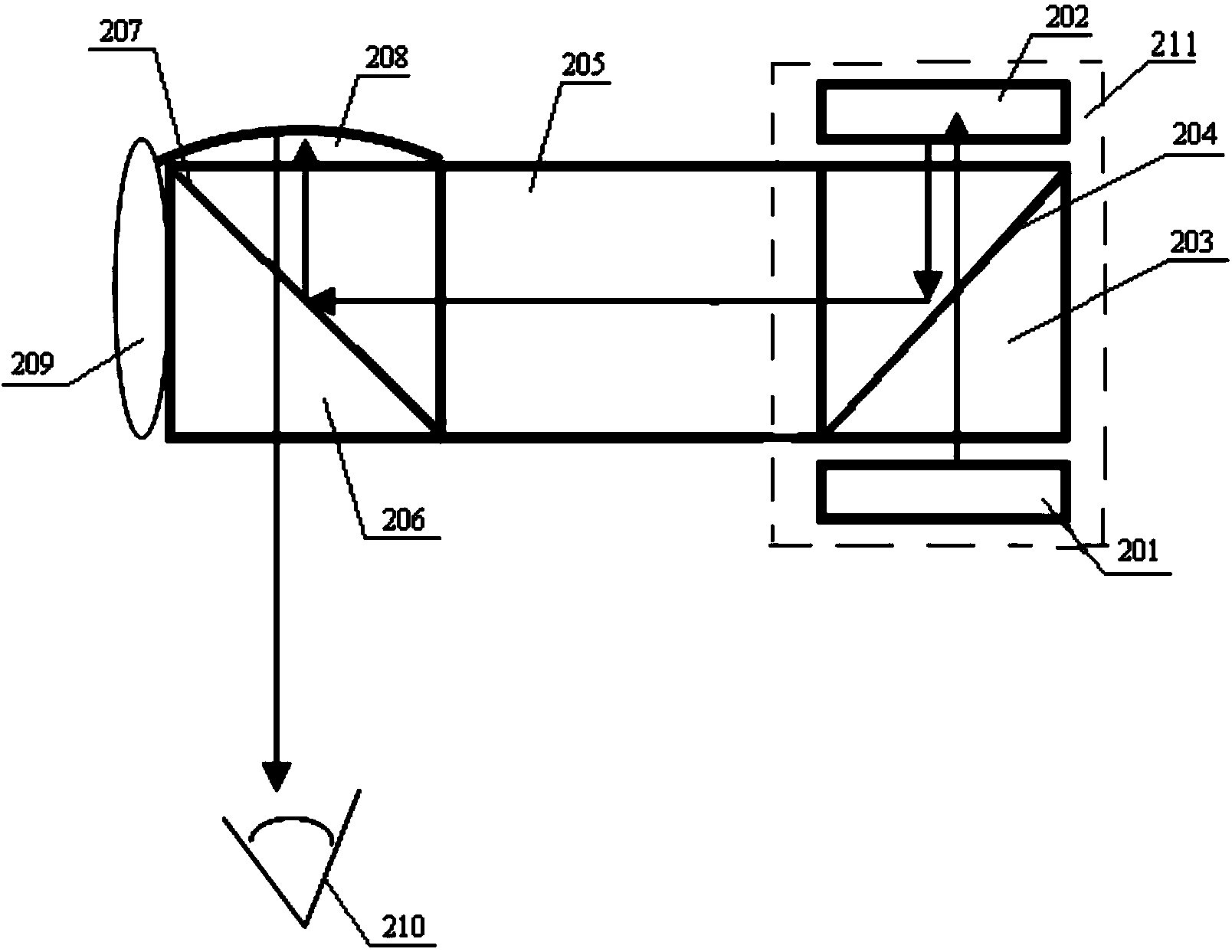
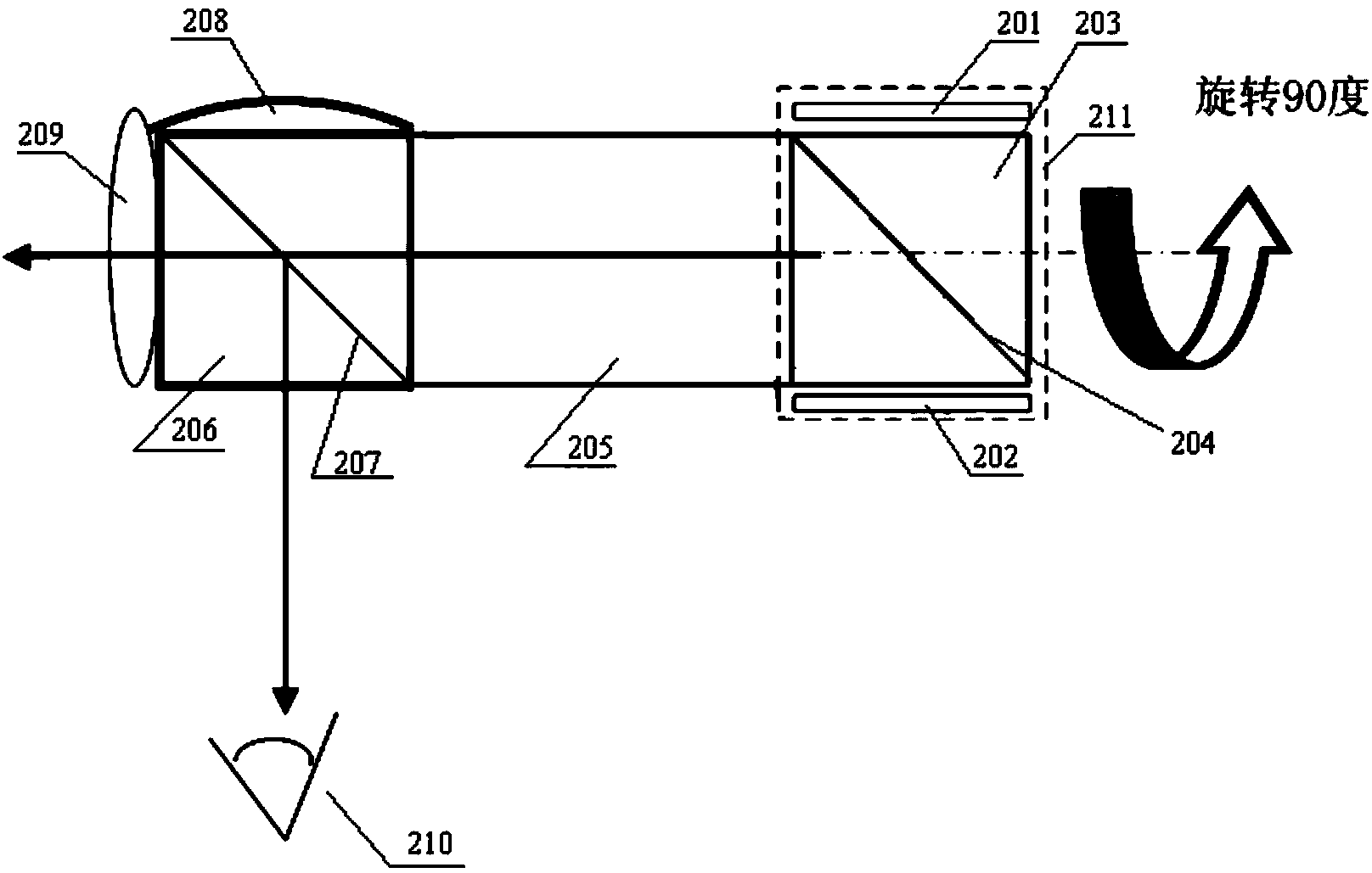
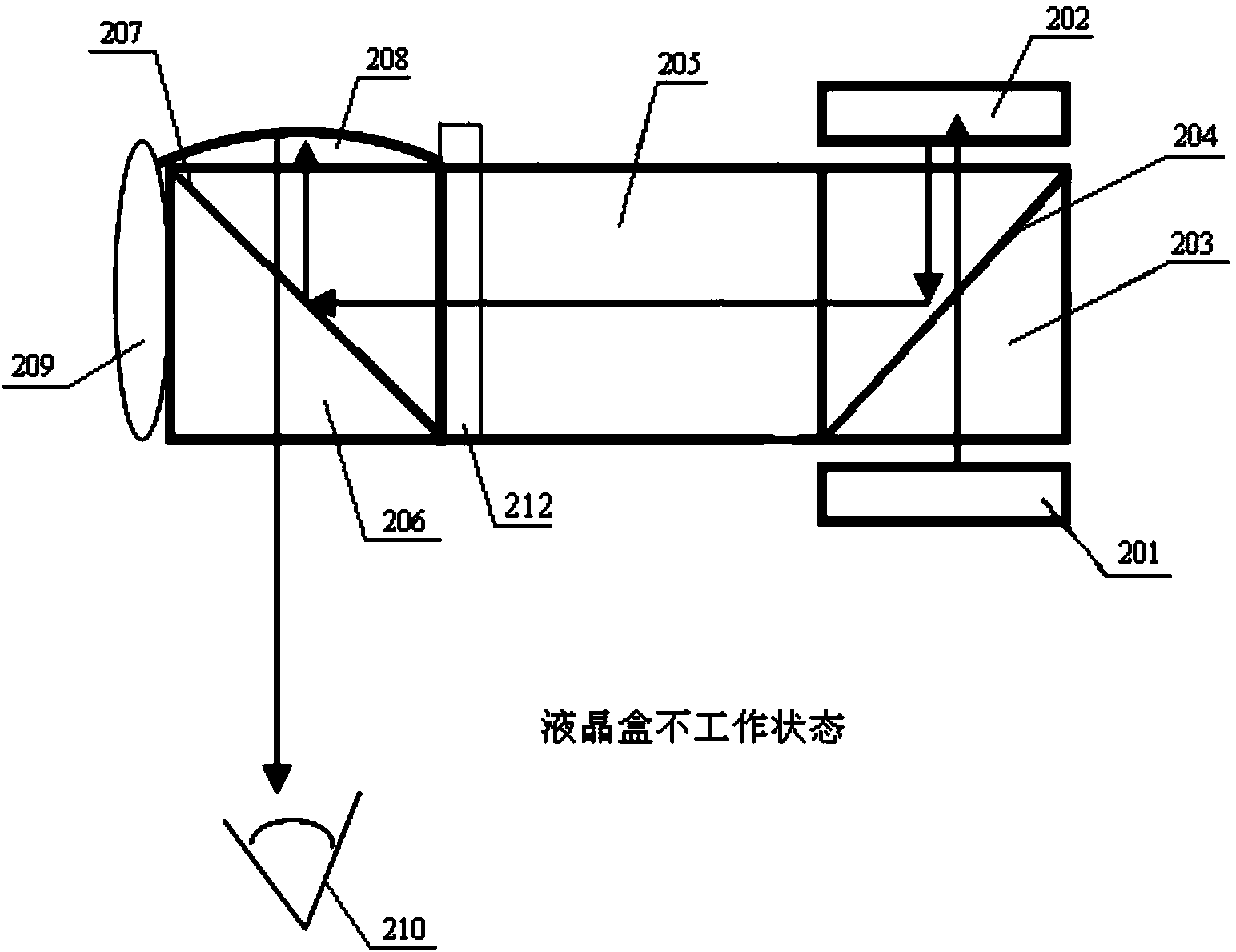
[0032] The working principle of this technical solution is: a conversion device is added to the display system. When the function of the projection system needs to be realized, the conversion device is in the working state to change the polarization state of the light output by the first polarization beam splitter, so that the light is incident on the In the projection lens, the image displayed on the display chip is projected for sharing. When the func...


PUM


Abstract

The invention provides a display system comprising a display chip, a first polarization beam splitter, a prism, a second polarization beam splitter, a reflection device, a projection lens and a conversion device. After light emitted by a light source passes through the first polarization beam splitter, P light in the light source enters the display chip. The display chip reflects the P light, the P light is converted into S light, and the S light enters the first polarization beam splitter. The first polarization beam splitter reflects the S light. When the conversion device is in a working state, the S light reflected by the first polarization beam splitter is converted into P light and the conversion device outputs the P light, or the polarization state of the S light reflected by the first polarization beam splitter does not change and the conversion device outputs the S light. When the conversion device outputs the S light, the S light is transmitted to the second polarization beam splitter through the prism. The second polarization beam splitter reflects the S light to the reflection device, and the S light is collimated and amplified by the reflection device and reflected to the human eye. When the conversion device outputs the P light, the P light passes through the second polarization beam splitter and enters the projection lens.

Description

technical field [0001] The invention relates to the field of optical instruments, in particular to a display system, which is mainly used for display systems with compact structures such as head-mounted visual devices. Background technique [0002] Head Mount Display can directly obtain two-dimensional images from LCD, OLED, LCOS and other micro-displays, and can also indirectly obtain two-dimensional images through optical fiber and other transmission methods. The image is imaged at infinity through the collimating lens, and then the image is reflected into the human eye through the reflective surface. Such products mainly have the characteristics of small size and light weight. However, at present, the head-mounted visual devices of Google, Epson, and Sony do not have the function of sharing the image content transmitted into the human eye with other people at the same time. This problem hinders the promotion and application of compact display systems such as head-mounte...

Claims


Application Information

Patent Timeline
Patent Type & Authority Applications(China)
IPC IPC(8): G02B27/28G02B27/01
Inventor 张鹏
Owner BEIJING LLVISION TECH CO LTD
Why Eureka
Try Eureka