Steel box girder incremental launching construction method based on walking type three-dimensional hydraulic incremental launching equipment

A technology of jacking equipment and jacking construction, which is applied in the erection/assembly of bridges, bridges, and bridge construction, etc., can solve the problems of labor and time-consuming, no automatic digital control, and difficulty in controlling the accuracy of jacking and closing.

CN109629440AActive Publication Date: 2019-04-16CHINA RAILWAY FIRST GRP CO LTD +1
8 Cites 3 Cited by

Patent Information

Authority / Receiving Office
CN · China
Current Assignee / Owner
Publication Date
2019-04-16

Smart Images

  • Figure 1
    Figure 1
  • Figure 2
    Figure 2
  • Figure 3
    Figure 3
Patent Text Reader

Abstract

The invention discloses a steel box girder incremental launching construction method based on walking type three-dimensional hydraulic incremental launching equipment. The two ends of a construction steel box girder are each supported on a girder end pier, and the construction steel box girder is divided into a first girder body and a second girder body with a midspan pier being the boundary; incremental launching construction includes the steps that 1, temporary piers and midspan temporary piers are constructed; 2, incremental launching is conducted on the girder bodies synchronously throughthe walking type three-dimensional hydraulic incremental launching equipment; 3, midspan closing is conducted. The walking type three-dimensional hydraulic incremental launching equipment is adopted for conducting incremental launching on the two girder bodies synchronously until the two girder bodies of the constructed steel box girder are closed from two sides to the midspand; incremental launching of the walking type three-dimensional hydraulic incremental launching equipment is easy and convenient to control, multiple sets of walking type three-dimensional hydraulic incremental launching equipment can easily and conveniently act synchronously, incremental launching positions are arranged flexibility, a guide beam and a slideway beam used for longitudinal incremental launching are not needed, self-balance incremental launching is really realized, and the process of incremental launching is safe and reliable.
Need to check novelty before this filing date? Find Prior Art

Description

technical field

[0001] The invention belongs to the technical field of bridge construction, in particular to a steel box girder jacking construction method based on walking three-dimensional hydraulic jacking equipment. Background technique

[0002] With the continuous improvement of my country's bridge design and construction technology, a large number of continuous steel box girder bridges have emerged in the fields of highways, urban transportation, and railways. The jacking method is widely used in its construction due to the advantages of less land occupation, no impact on the traffic under the bridge, no need for large lifting equipment, safety and reliability, and low cost. The jacking method construction is to set up a prefabricated field behind the abutment along the bridge axis direction, and set up steel guide beams, temporary piers, slideways, horizontal jacks (also called jacking force devices or jacking force devices), etc., the actual During construction, aft...

Examples

Embodiment Construction

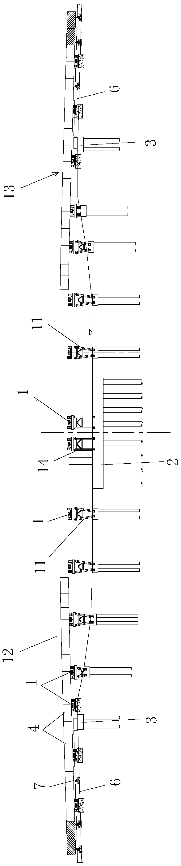
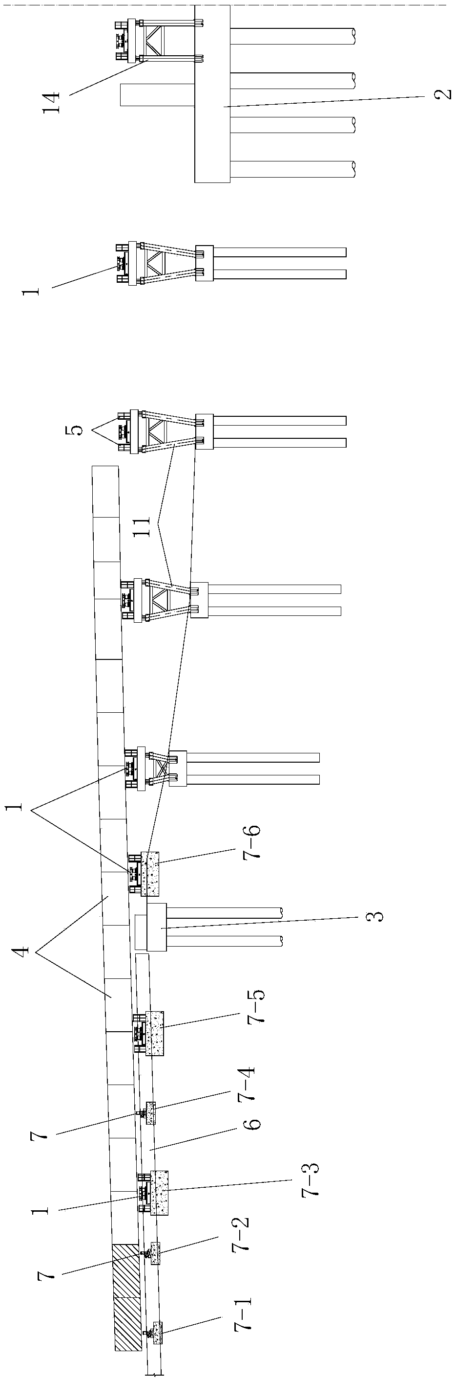
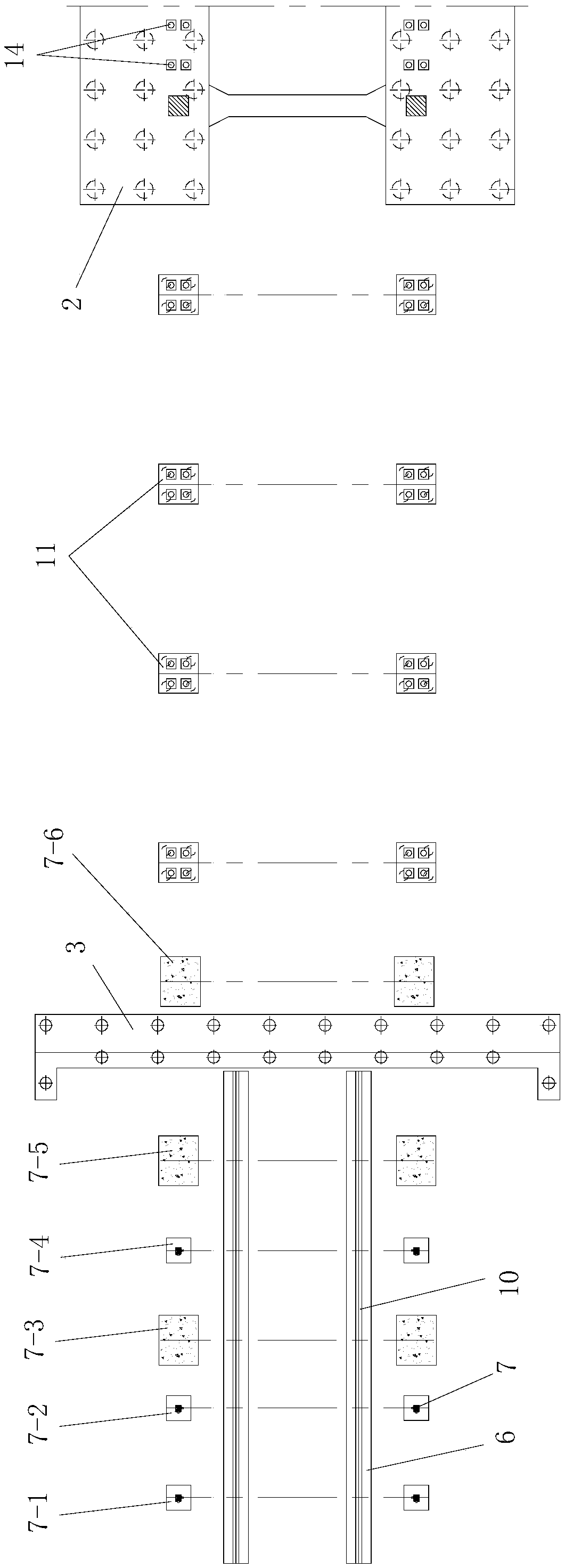
[0108] Such as Figure 19 Shown is a steel box girder jacking construction method based on walking-type three-dimensional hydraulic jacking equipment. There is a mid-span pier 2 between them, and the two beam end piers 3 are arranged symmetrically on both sides of the mid-span pier 2; the constructed steel box girder is divided into the first beam body with the mid-span pier 2 12 and the second beam body 13, the first beam body 12 and the second beam body 13 are arranged symmetrically and both have the same structure and size; the first beam body 12 and the second beam body 13 are made of A steel box girder formed by splicing a plurality of steel box girder segments 4 from front to back, the mid-span pier 2 and the beam end pier 3 are both vertically arranged permanent piers and both are reinforced concrete Support pier, the front ends of the first beam body 12 and the second beam body 13 are supported on the mid-span support pier 2 and the rear ends of the two are supported ...