LED digital tube display and button control chip using time division multiplexing technology

A LED digital tube and time-division multiplexing technology, which is applied to static indicators, instruments, etc., can solve the problems of unfavorable anti-interference performance of key control, increase of control chip wafer area, faint brightness of luminous display segments, etc., to solve the problem of faint brightness of corresponding luminous display segments , optimize cost, optimize the effect of quantity

Active Publication Date: 2016-07-27
FUZHOU FUDA HISI MICROELECTRONICS
View PDF7 Cites 0 Cited by
  • Summary
  • Abstract
  • Description
  • Claims
  • Application Information

AI Technical Summary

Problems solved by technology

Too many output pins will increase the wafer area of ​​the control chip and increase the packaging cost
Most of the display driver and key control chips of traditional LED dig...

Method used


Image

  • LED digital tube display and button control chip using time division multiplexing technology
  • LED digital tube display and button control chip using time division multiplexing technology
  • LED digital tube display and button control chip using time division multiplexing technology

Examples


Embodiment Construction

[0028] The present invention will be further described below in conjunction with the specific embodiments of the accompanying drawings. (but not limitation of the invention).

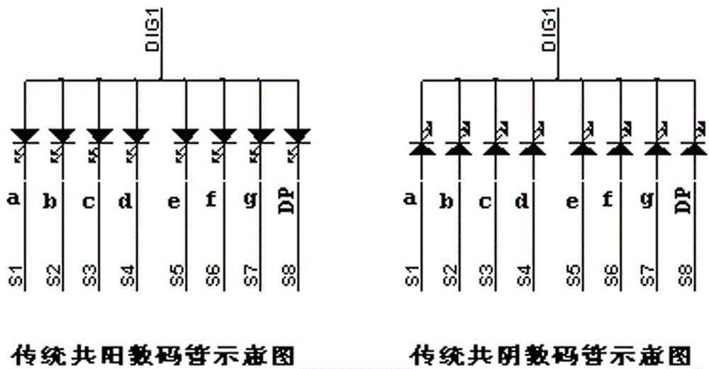
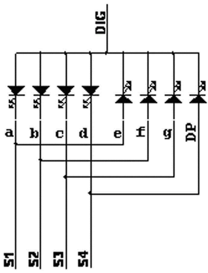
[0029] Such as figure 1 As shown, it is the wiring diagram of the traditional common cathode and common anode digital tubes or LED light-emitting tube array, and it is a 1-digit * 8-segment display. A total of N+P=1+8=9 control pins are required, and figure 2 It is the wiring diagram of the nixie tube or LED light-emitting array used in the example of the present invention. It can be seen that the same 1-digit 8-segment display control only needs N+V=1+4=5 control pins. It can save 4 control pins of the upper computer control chip, and also save the same number of digital tube packaging pins, saving system costs in all directions.

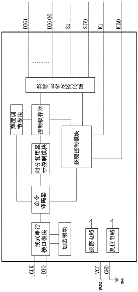
[0030] image 3 It is a block diagram of the internal structure of the chip of the present invention. The chip of the present invention is provided with a two-wire seri...


PUM


Abstract

The invention relates to an LED digital tube display and button control chip adopting time-division multiplexing technology. After the LED digital tube display and button control chip adopting time-division multiplexing technology is combined and connected to the LED digital tube or LED light-emitting tube array, the cost of the traditional LED digital tube display drive control system is optimized, and the anti-interference of the key control is optimized at the same time. Performance and the problem of the corresponding light-emitting segment displaying slightly bright during the button action; the present invention adopts time-division multiplexing technology, and after the digital tube or LED light-emitting tube array is combined and connected with common cathode and common anode, it is time-divisionally controlled. At the same time, each display output lead The pins are time-division multiplexed as button scanning output to realize the combination button control function of (N+V)*M, (M is the number of combination button input pins); the invention adopts independent button input pins, abandoning the traditional DIG pin When the pin is multiplexed as a key input, in principle, there is an unavoidable high-impedance state or the problem that the corresponding luminous display segment is slightly bright when the key is pressed, so as to improve the anti-interference performance of the key.

Description

technical field [0001] The invention relates to an LED digital tube display and button control chip adopting time-division multiplexing technology. Background technique [0002] Traditional nixie tube or LED light-emitting tube array display driver, due to the constraints of traditional nixie tube packaging technology, requires a large driver pin interface for control. Taking the N-bit P-segment digital tube or N*P light-emitting tube display array driven by the present invention as an example, at least N+P control pins are required. Too many output pins will increase the wafer area of ​​the control chip and increase the packaging cost. Most of the display driver and key control chips of traditional LED digital tubes use DIG pins as key input multiplexing. , there will be a problem that the corresponding light-emitting display segment of the button action interval is slightly bright. Therefore, considering the above factors, it is necessary to carry out some reform and in...

Claims


Application Information

Patent Timeline
IPC IPC(8): G09G3/14
Inventor 刘伟城
Owner FUZHOU FUDA HISI MICROELECTRONICS
Why Eureka
Try Eureka