Hand-held automatic binding tool

A handheld, automatic technology, applied in the direction of strapping materials, parts of strapping machinery, packaging, etc., can solve the problems of low work efficiency and high labor intensity, and achieve the effect of improving efficiency, reducing labor intensity, and small size of gun head

Active Publication Date: 2014-11-19
SHENZHEN SWIFT AUTOMATION TECH CO LTD
View PDF6 Cites 25 Cited by
  • Summary
  • Abstract
  • Description
  • Claims
  • Application Information

AI Technical Summary

Problems solved by technology

[0004] The purpose of this invention is to solve the problem that there are manual cable tie guns on the market, which have no power, rely on manual leverage to tighten and use the sudden mechanism to cut off the tail of the cable tie. A manual cable tie gun still needs to manually take the cable tie, manually perforate it, and then use the manual cable tie gun after a little tension, which is a new type of hand-held automatic cable tie tool due to the shortage of low work efficiency and high labor intensity.

Method used


Image

  • Hand-held automatic binding tool
  • Hand-held automatic binding tool
  • Hand-held automatic binding tool

Examples


Embodiment 1

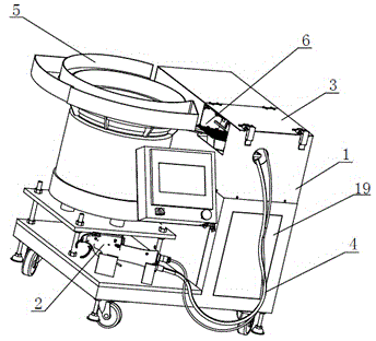
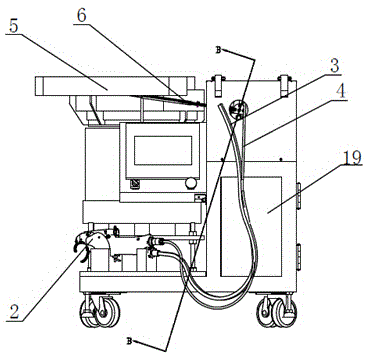
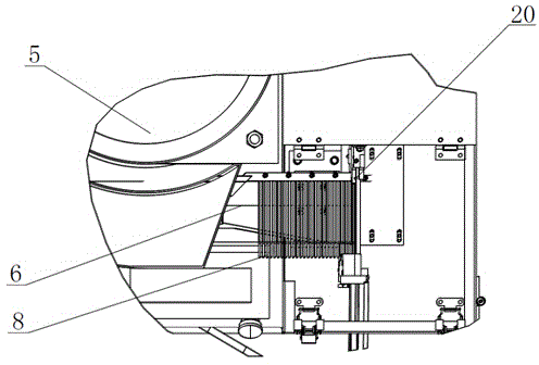
[0036] Such as figure 1 , figure 2 , image 3 , Figure 4 , Figure 5 , Image 6 , Figure 7 , Figure 8 , Figure 9 , Figure 10 , Figure 11 , Figure 12 Shown: a hand-held automatic cable tie tool, including a host 1, a gun head 2, a feeding tube 3 and a data line 4, the host 1 is connected to the gun head 2 through the feeding tube 3 and the data line 4, the The main engine 1 includes a pusher cylinder 11, a pusher cylinder seat 12, a pusher block 13, a guide block 15, a feed pipe connector 16, a valve 17, a valve cylinder 18, an electric control and an air control system 19. An electric control and air control system 19 is provided, the feeding pipe 3 is connected above the right end of the main machine 1, and a valve 17 is provided below the port where the feeding pipe 3 is connected to the main machine 1;

[0037] A valve cylinder 18 is provided below the valve 17, a feed pipe connector 16 is provided above the valve 17, a guide block 15 is provided behind ...


PUM


Abstract

The invention provides a hand-held automatic binding tool which comprises a main machine, a gun head, a feeding pipe and a data line. The main machine is connected with the gun head through the feeding pipe and the data line. The hand-held automatic binding tool further comprises a vibrating plate and straight vibrator. The vibrating plate is located on the left side of the main machine. The straight vibrator is connected to the right side of the vibrating plate. The straight vibrator is connected with a pushing chamber. The vibrating plate screens and sorts bulk binding bands. When an optical fiber sensor detects that the front-most binding band is in position, an air cylinder pushes the front-most binding band into the feeding pipe, a trigger is pulled to allow compressed air to feed the binding band into the gun head, and the gun head completes winding, perforating, tightening and cutting off. The hand-held automatic binding tool has the advantages that binding efficiency is increased greatly, binding can be completed while hands are not in contact with the binding bands, labor intensity of workers is relieved greatly, the gun head is small in size and lightweight, and the gun head is connected with main machine through the flexible pipeline.

Description

technical field [0001] The invention relates to an automatic tie tool, in particular to a hand-held automatic tie tool. Background technique [0002] At present, the binding of wires and pipelines with cable ties is mostly done manually. There are manual cable tie guns on the market, which have no power. The cable tie gun still needs to manually take the cable tie, manually perforate it, and then use the manual cable tie gun after a little tension. The work efficiency is low and the labor intensity is high. Generally, a working cycle takes 7-10 seconds; [0003] There is also a desktop cable tie machine on the market. This machine has the following disadvantages: 1. The machine is fixed and can only move the workpiece. It is not flexible to use and is only suitable for small batch production; 2. Due to space constraints, it cannot be used for On-site or internal construction of aircraft, ships, trains, automobiles, household appliances, communication equipment pipelines,...

Claims


Application Information

Patent Timeline
Patent Type & Authority Applications(China)
IPC IPC(8): B65B27/06B65B13/06B65B13/22B65B13/18
Inventor 许修义
Owner SHENZHEN SWIFT AUTOMATION TECH CO LTD
Why Eureka
Try Eureka