Double-vacuum-layer glass getter sealed placement structure and manufacturing method thereof

A vacuum glass and getter technology, which is applied in glass forming, glass re-molding, glass manufacturing equipment and other directions, can solve the complex encapsulation and placement process of the getter, the difficulty of placing the getter, and the small amount of getter. and other problems, to achieve the effect of simple structure, low cost and high degree of vacuum

Inactive Publication Date: 2015-01-21
戴长虹
View PDF4 Cites 0 Cited by
  • Summary
  • Abstract
  • Description
  • Claims
  • Application Information

AI Technical Summary

Problems solved by technology

Due to the small space in the vacuum layer of vacuum glass and the transparency of the glass, the protection and activation of the getter needs to be considered, so it is very difficult to place the getter in the vacuum layer
The traditional method of placing the getter in the vacuum glass is to first package the getter under vacuum, and then place it in the groove pre-opened on the glass. After sealing the edge of the vacuum glass, vacuuming, and sealing the suction port , and then use laser or infrared rays to open the package of the getter to activate the getter. The disadvantage of this method is that the encapsulation and placement process of the getter is complicated, the amount of the getter is small, and the appearance and mechanical properties of the glass are affected.

Method used


Image

  • Double-vacuum-layer glass getter sealed placement structure and manufacturing method thereof

Examples


Embodiment

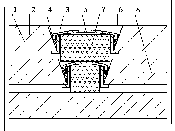
[0044]Embodiment: Referring to the accompanying drawings, the vacuum glass is composed of an upper glass 1, a lower glass 2 and a middle glass 8. A through hole is respectively drilled on the upper glass 1 and the middle glass 8 to form a suction port, wherein the through hole on the upper glass 1 is larger than the middle glass. through holes on the glass 8; a metal round tube 3 is prepared and inserted into the air intake port, and the outer sides of the bottom of the round tube 3 are welded to the upper glass 1 and the middle glass 8 by glass solder or metal paste respectively, and the outer sides of the round tube 3 The upper part and the suction port form a sealing groove 4, and the top of the round tube 3 is lower than the upper surface of the upper glass 1 and the middle glass 8 respectively; a sealing cover 5 is made according to the size of the sealing groove 4, and the edge of the sealing cover 5 can be inserted into the sealing In the groove 4, the height of the seal...


PUM


Abstract

The invention relates to a double-vacuum-layer glass getter sealed placement structure. The structure has the following characteristics: one round hole is drilled on each of the upper glass and the intermediate glass of vacuum glass, such that air-exhaust ports are prepared; one round pipe is prepared and is inserted in each of the air-exhaust ports; the lower parts of the round pipes are welded with glass, and the upper parts of the round pipes form sealing grooves with the air-exhaust ports; sealing caps are provided on the upper parts of the sealing grooves; the edges of the sealing caps are inserted into the sealing grooves; when the glass is edge-sealed; a getter is placed into the air-exhaust ports, and the ports are covered by using the sealing caps; a metal solder is placed in the sealing grooves or on the sealing caps; the air-exhaust ports are vacuumed and heated, such that the getter is automatically activated under high temperature and high vacuum, and also the metal solder is molten into liquid under the high temperature; the liquid is retained in the sealing grooves, and the edges of the sealing caps are immersed in the liquid; the air-exhaust ports are automatically sealed with a liquid sealing principle, and the getter is sealed in the vacuum layers. The method provided by the invention is suitable for mass productions. With the method, vacuum glass production efficiency and qualification rate can be greatly improved, and production cost can be reduced.

Description

technical field [0001] The invention belongs to the field of vacuum glass, and in particular relates to a sealed placement structure of a double-vacuum layer glass getter and a manufacturing method thereof. [0002] Background technique [0003] The existing vacuum glass is generally composed of two or three pieces of flat glass. The glass is sealed with low-temperature glass solder around the edges, and there is a tiny support in the middle. A thin layer of 0.1-0.2mm thickness is formed between the two pieces of glass by pumping air. Vacuum layer. Since there is no heat and sound transmission of gas, and the inner surface of the glass can have a transparent low-heat radiation film, the vacuum glass has good heat insulation and sound insulation effects, and is one of the best performance energy-saving glasses. [0004] The key technologies of the existing vacuum glass include: one is edge sealing, the other is the placement of supports, and the third is the acquisition and...

Claims


Application Information

Patent Timeline
Patent Type & Authority Applications(China)
IPC IPC(8): C03B23/24C03C27/08
CPCY02P40/57
Inventor 戴长虹
Owner 戴长虹
Why Eureka
Try Eureka