Line throwing device special for power transmission

A rope thrower, a pulling line technology, applied in the direction of overhead lines/cable equipment, etc., can solve the problems of inability to adjust, fixed range, troublesome operation, etc.

Inactive Publication Date: 2015-01-28
STATE GRID CORP OF CHINA +1
View PDF8 Cites 3 Cited by
  • Summary
  • Abstract
  • Description
  • Claims
  • Application Information

AI Technical Summary

Problems solved by technology

However, it has two disadvantages: first, the range is fixed and cannot be adjusted according to the actual height of the tree; trouble

Method used


Image

  • Line throwing device special for power transmission

Examples


Embodiment Construction

[0020] The special rope throwing device for power transmission of the present invention will be described in detail below in conjunction with the accompanying drawings.

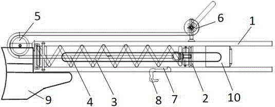
[0021] See attached figure 1 The special rope throwing device for power transmission includes a conduit 1 . The front end of the conduit 1 is open to allow a weight 10 connected to a lead wire (not shown) to be ejected therefrom. The rear end of the catheter 1 has a tail (not marked). A piston 2 is accommodated in the conduit 1 , and a spring 3 is connected between the piston 2 and the tail of the conduit 1 . When the piston 2 moves towards the tail of the catheter 1, the spring 3 is compressed. The pulling wire 4 passes through the tail of the guide tube 1 and is connected with the piston 2 , and its other end is connected with the wire tightener 6 around the pulley 5 arranged at the rear end of the guide tube 1 . Therefore, rotating the tensioner 6 pulls the piston 2 backwards through the pull wire ...


PUM


Abstract

The invention provides a line throwing device special for power transmission. The line throwing device special for the power transmission comprises a conduit, wherein the front end of the conduit is open, and the rear end of the conduit is provided with a tail. A piston with a positioning portion is contained in the conduit. An elastic element is connected between the tail of the conduit and the piston. One end of a pull line passes through the tail of the conduit and is connected with the piston. The other end of the pull line is connected with a tight heaving device through a guiding element. A trigger movement groove is further formed in the conduit. A trigger clamped with the positioning portion of the piston is movably arranged in the trigger movement groove. The line throwing device special for the power transmission pulls the piston to compress the elastic element through the pull line, does not need an external object, and not only is convenient, but also saves labor. Additionally, the trigger of the line throwing device special for the power transmission can move forward and backward along the trigger movement groove, and therefore the deformation quantity of the elastic element can be adjusted, and then a firing range can be adjusted, and the line throwing device special for the power transmission is suitable for actual use.

Description

[0001] technical field [0002] The invention belongs to the technical field of installation and maintenance tools for transmission lines, and in particular relates to a tool for rope-throwing operation of high-voltage transmission lines. [0003] Background technique [0004] With the development of urban building construction and road network construction, the scale of my country's power grid continues to expand. During the construction and maintenance of transmission lines, surrounding tall trees often affect the safety of transmission lines. Therefore, these trees need to be felled. In tree felling operations, the key to ensuring the safety of electrical equipment and operators is to control the falling direction of trees. Generally, the tether method is used to control the falling direction of trees. For tall trees, in order to effectively control the trees from falling, it is necessary to tie the control rope high enough. [0005] At present, the commonly used t...

Claims


Application Information

Patent Timeline
Patent Type & Authority Applications(China)
IPC IPC(8): H02G1/02
Inventor 张明李庆兴刘广州吴国军武继雷吴伟廖志斌张大车叶辉于启万周燕青孙大校李运峰饶金阁
Owner STATE GRID CORP OF CHINA
Why Eureka
Try Eureka