Torque transmission joint and electric power steering device

A torque transmission and axial technology, applied in the transmission device, gear transmission device, power steering mechanism, etc., can solve the problems of reduced operating efficiency, increased frictional resistance, and reduced transmission efficiency, so as to improve operating efficiency, reduce costs, and improve The effect of recognition

Active Publication Date: 2015-02-04
NSK LTD
View PDF12 Cites 14 Cited by
  • Summary
  • Abstract
  • Description
  • Claims
  • Application Information

AI Technical Summary

Problems solved by technology

Therefore, also in the torque transmission joint 15 , there is a problem that the working efficiency of the inspection process for preventing the cushioning member 18 from being forgotten to be assembled is likely to decrease because it is difficult to visually confirm the cushioning member 18 .
Therefore, a force in a stretching direction acts on the cylindrical portion 24, and the cylindrical portion 24 becomes difficult to elastically deform in the radial direction, so it is difficult for the buffer member 18 to sufficiently absorb the alignment error. Part of the abutting portion where the surface abuts against the inner peripheral side surfaces of the driving side arm portion 21 and the driven side arm portion 23, the surface pressure becomes too large, and the frictional resistance of this portion increases, which may cause the electric power steering device to The transfer efficiency of the whole system drops
[0010] In addition, Japanese Patent No. 4779358 describes a structure in which a cushioning member is composed of three members superimposed in the axial direction, but in this structure, the clamped portion constituting the cushioning member is also arranged in a radial direction, so Difficult to adequately absorb alignment errors, etc.

Method used


Image

  • Torque transmission joint and electric power steering device
  • Torque transmission joint and electric power steering device
  • Torque transmission joint and electric power steering device

Examples


Embodiment Construction

[0093] The first example of embodiment

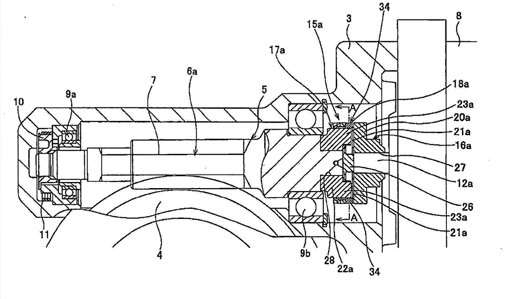
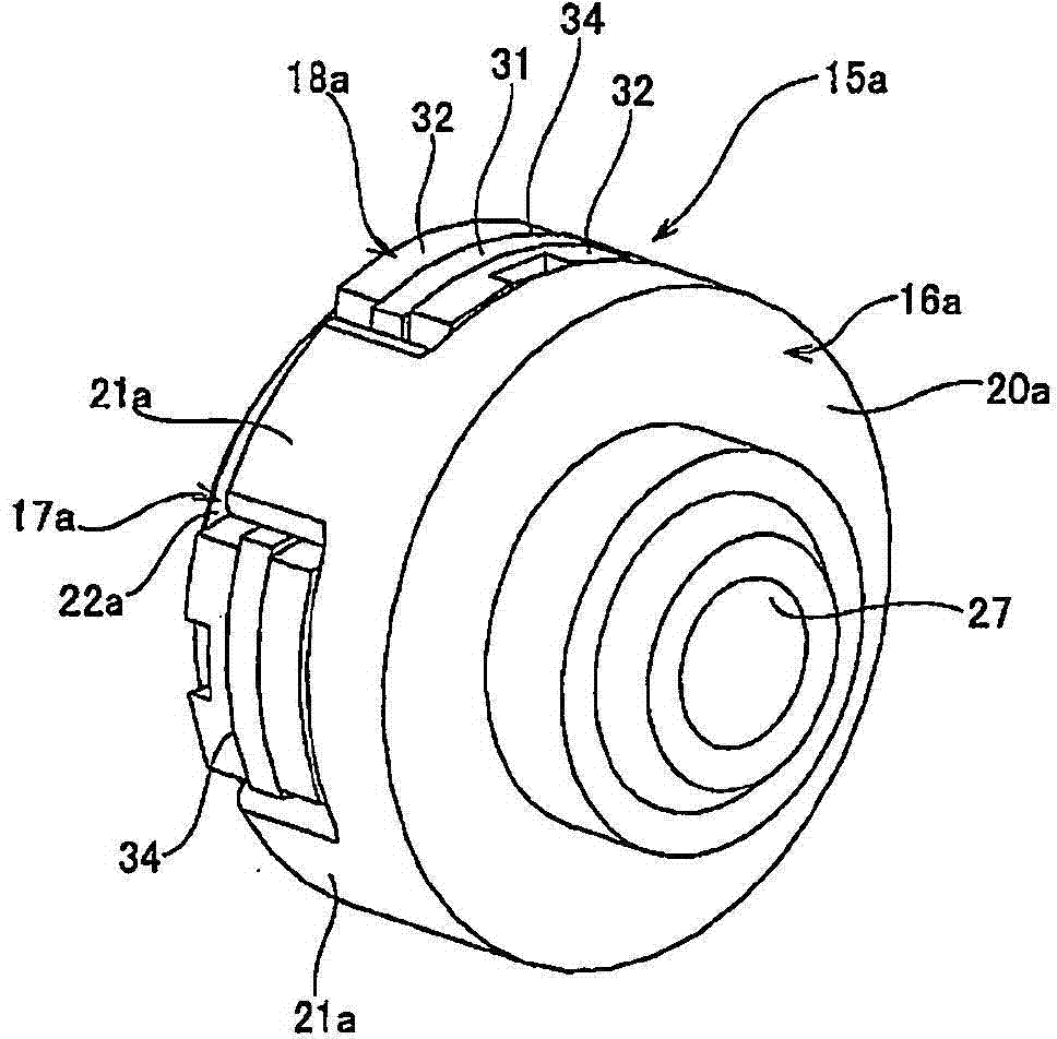
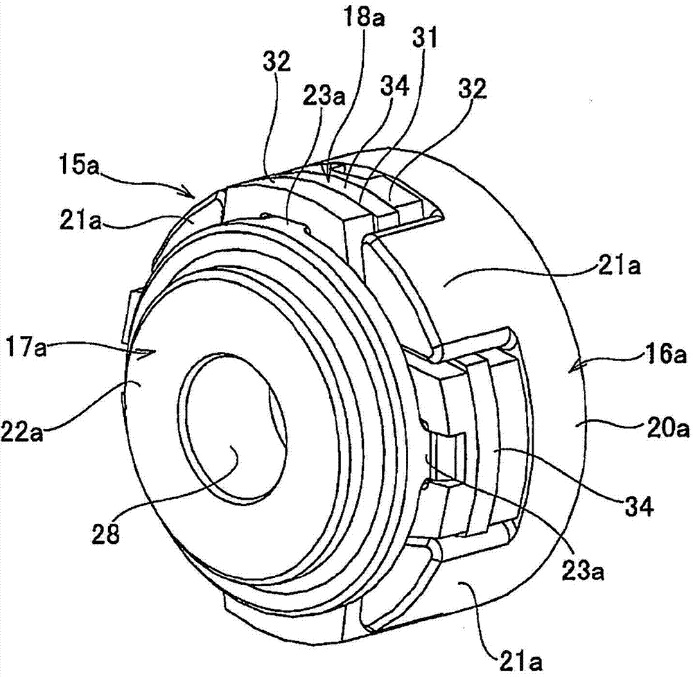
[0094] Figure 1 to Figure 16 The first example of the embodiment of the present invention is shown. The electric power steering device of this example basically also includes: a casing 3, which is supported on a fixed part of the vehicle (the vehicle body or a part fixed to the vehicle body), and does not rotate; Freely arranged in the housing 3, the steering shaft 2 is rotated by the operation of the steering wheel 1, and the steering shaft 2 applies a steering angle to the steering wheel as it rotates; the worm 5 includes a worm wheel 4, a worm shaft 6a and a worm tooth 7, The worm wheel 4 is supported on a part of the steering shaft 2 concentrically with the steering shaft 2 inside the casing 3, and the worm wheel 4 rotates together with the steering shaft 2. The worm gear 7 is provided at the axially intermediate portion of the worm shaft 6a, and is used to In the state where the worm gear 7 is meshed with the worm wheel 4, the a...


PUM


Abstract

[Problem] To provide a torque transmission joint (15a) that can reduce the thrust force transmitted between a worm shaft (6a) and the output shaft (12a) of an electric motor (8) without generating noise. A buffer member (18a) made of an elastic material is inserted between a drive-side transmission member (16a) supported at the output shaft (12a) and a driven-side transmission member (17a) supported at the worm shaft (6a). Sandwiched sections (33a, 33b) configuring the buffer member (18a) are interposed between: the peripheral direction lateral surface of a drive-side arm (21a) configuring the drive-side transmission member (16); and the peripheral direction lateral surface of a driven-side arm (23a) configuring the driven-side transmission member (17a). A damper (26) is integrally provided to the buffer member (18a), and the damper (26) is elastically sandwiched between the tip-end surface of the output shaft (12a) and the base-end surface of the worm shaft (6a).

Description

technical field [0001] The present invention relates to an electric power steering device and a joint for torque transmission. It is used to transmit torque between a drive shaft and a driven shaft in various mechanical devices including the electric power steering device. Background technique [0002] A power steering device is widely used in order to reduce the force required by the driver to operate the steering wheel when applying a steering angle to the steering wheels (usually the front wheels, except for special vehicles such as forklifts). As a power steering device, an electric power steering device using an electric motor as an auxiliary power source has also been rapidly popularized in recent years. Generally, in an electric power steering device, an auxiliary power of an electric motor is applied to the rotating shaft via a speed reducer to the rotating shaft that rotates by the operation of the steering wheel and imparts a steering angle to the steering wheel a...

Claims


Application Information

Patent Timeline
Patent Type & Authority Applications(China)
IPC IPC(8): F16D3/68B62D5/04F16D3/12F16F15/136
CPCF16F15/136F16D3/68B62D5/0409F16H1/16F16F15/1245B62D5/0454B62D7/224
Inventor 森山诚一小岛和彦
Owner NSK LTD
Why Eureka
Try Eureka