Small hole punch anti-break punching die

An anti-breakage and punching technology, which is applied in the field of punching dies, can solve problems such as the inability to guarantee product production stability, affect production and processing efficiency, and easy breakage of small hole punches, achieve quick disassembly and installation, and reduce mold repair time , the effect of reducing production costs

Active Publication Date: 2016-07-13
JIANGSU BOJUN IND TECH
View PDF9 Cites 1 Cited by
  • Summary
  • Abstract
  • Description
  • Claims
  • Application Information

AI Technical Summary

Problems solved by technology

Stainless steel plate is a commonly used stamping material. There is a problem that the punch is easy to break when punching small holes on thick stainless steel plates. For example, when punching small holes with a diameter of 1.0mm on a 2.0mm thick stainless steel plate, due to The head is slender and the stainless steel plate is thick, so it is easy to break the punch when punching small holes on the stainless steel plate
In order to prevent the small hole punch from breaking, a three-stage A punch is usually used, and the radial width from narrow to wide is the first sub-punch, the second sub-punch and the third sub-punch, and the three-stage A punch passes through the upper Plywood, stopper plate and stripper plate, in which the thinner first sub-punch is completely located in the stripper plate, and a sheath is placed outside the first sub-punch. The small hole punch of this structure reduces to a certain extent However, when punching a small hole with a diameter of 1.0mm, because the punch is long and the stainless steel plate is thick, the small hole punch is still easy to break, resulting in frequent replacement of the punch and easy damage to the template. Affects the efficiency of production and processing, resulting in an increase in product production costs, and cannot guarantee the stability of product production

Method used


Image

  • Small hole punch anti-break punching die
  • Small hole punch anti-break punching die
  • Small hole punch anti-break punching die

Examples


Embodiment Construction

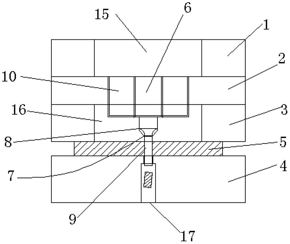
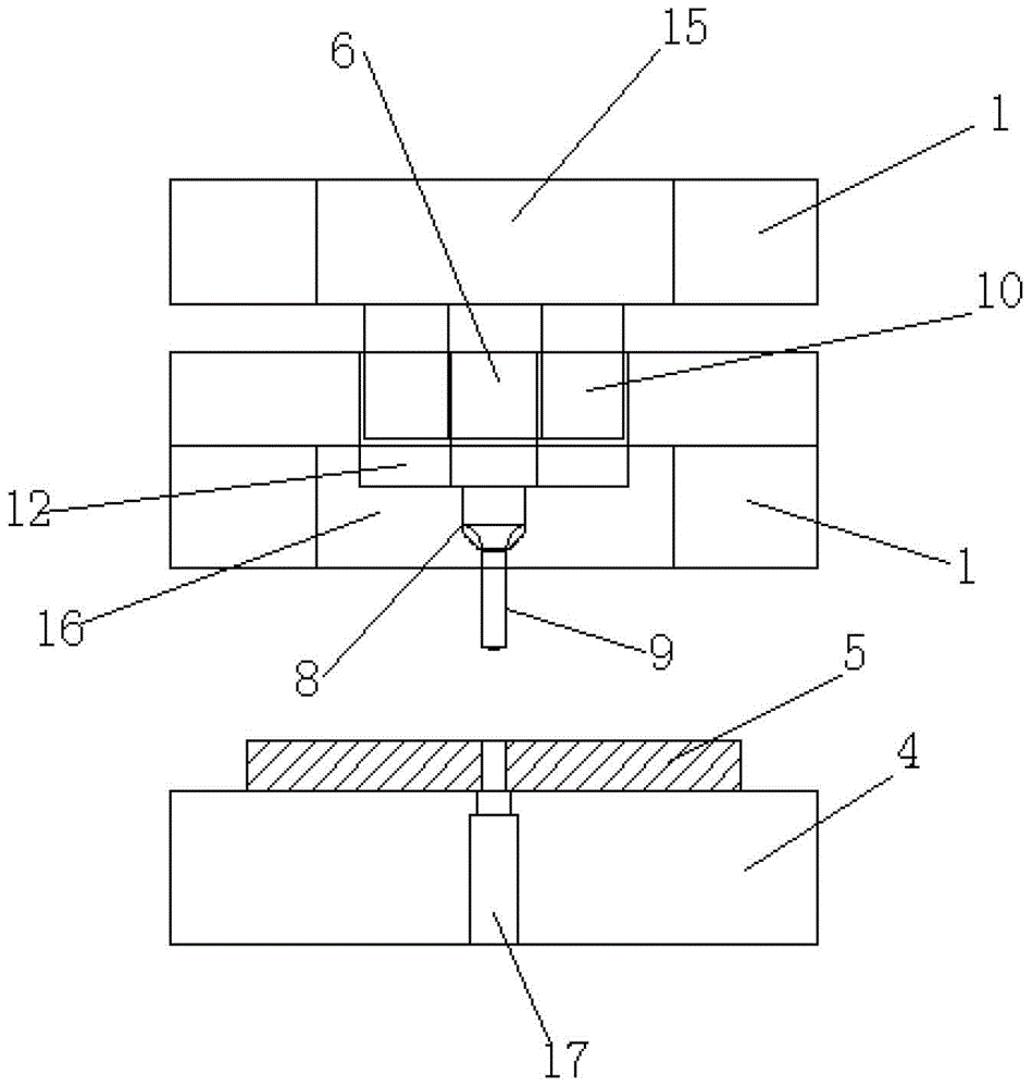
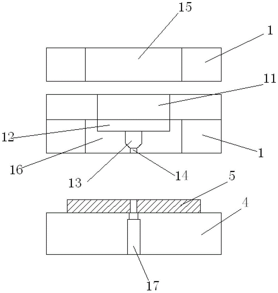
[0024] Such as figure 1 , figure 2 and image 3 As shown, a small hole punch anti-break punching die includes an upper die and a lower die, and the upper die includes an upper splint 1, a stopper plate 2 and a stripper plate 3 positioned sequentially from top to bottom; There is an elastic space between the upper splint and the stop plate, the lower mold includes a lower template 4, and the product 5 to be punched is arranged between the stripper plate and the lower template, and a two-stage Punch, the punch includes a cylindrical punching rod 6 and a stepped sub-punch 7 arranged below the cylindrical punching rod, the sub-punch includes a stopper 8 and a stopper below the stopper Punch portion 9, the radial width of the punch portion is smaller than the radial width of the stop portion, the radial width of the punch portion is smaller than the radial width of the columnar rod, and the columnar rod Pass through the stopper plate and be positioned in the stripper plate, the...


PUM


Abstract

The invention discloses a small hole punch breaking prevention punching die. The die comprises an upper die and a lower die, wherein the upper die comprises an upper clamping plate, a stopping plate and a stripper plate; an elastic space is defined between the upper clamping plate and the stopping plate; the lower die comprises a lower die plate, and a two-segment punch; the punch comprises a columnar knocking rod and a sub-punch which comprises a stopping part and a punch part which is positioned below the stopping part; the radial width of the punch part is smaller than that of the stopping part, and the radial width of the punch part is smaller than that of the knocking rod which penetrates through the stopping plate to be positioned in the stripper plate; the stopping part is positioned in the stripper plate, and the punch part penetrates through the stripper plate; corresponding to the punch part, a waste passing hole is formed in the lower die plate. According to the invention, the breaking loss of the punch can be effectively reduced, the die repairing time is shortened, the high safety of the die is guaranteed, the production efficiency is improved, the production stability is ensured, additional waste during product production can be avoided, the purpose of reducing the production cost of the product is achieved, and the punching die is more convenient to disassemble, assemble and replace.

Description

technical field [0001] The invention relates to a punching die, in particular to an anti-break punching die for a small hole punch. Background technique [0002] The punching die is a die that separates the waste material along the closed contour to obtain a workpiece with a hole on the blank or sheet. Stainless steel plate is a commonly used stamping material. There is a problem that the punch is easy to break when punching small holes on thick stainless steel plates. For example, when punching small holes with a diameter of 1.0mm on a 2.0mm thick stainless steel plate, due to The head is slender and the stainless steel plate is thick, so it is easy to break the punch when punching small holes on the stainless steel plate. In order to prevent the small hole punch from breaking, a three-stage A punch is usually used, and the radial width from narrow to wide is the first sub-punch, the second sub-punch and the third sub-punch, and the three-stage A punch passes through the u...

Claims


Application Information

Patent Timeline
Patent Type & Authority Patents(China)
IPC IPC(8): B21D28/34
CPCB21D28/34
Inventor 巴继安
Owner JIANGSU BOJUN IND TECH
Why Eureka
Try Eureka