
Special-shaped small punching punch anti-break punching die

A punching and breaking prevention technology, applied in the field of punching molds, can solve the problems of inability to guarantee the production stability of products, complex shapes of special-shaped holes, affecting production and processing efficiency, etc., to achieve simple structure and reduce mold repair time. , Reduce the effect of breaking damage

Active Publication Date: 2015-12-23
JIANGSU BOJUN IND TECH
View PDF6 Cites 0 Cited by
  • Summary
  • Abstract
  • Description
  • Claims
  • Application Information

AI Technical Summary

Problems solved by technology

However, when the above-mentioned structure is used for punching special-shaped small holes, due to the complex shape of the special-shaped small holes, the punches of the corresponding shape are easily broken at the hanging pins, resulting in frequent replacement of punches and easy damage to the template, thereby affecting production and processing efficiency. , resulting in an increase in product production costs, and the stability of product production cannot be guaranteed

Method used


Image

  • Special-shaped small punching punch anti-break punching die
  • Special-shaped small punching punch anti-break punching die
  • Special-shaped small punching punch anti-break punching die

Examples


Embodiment Construction

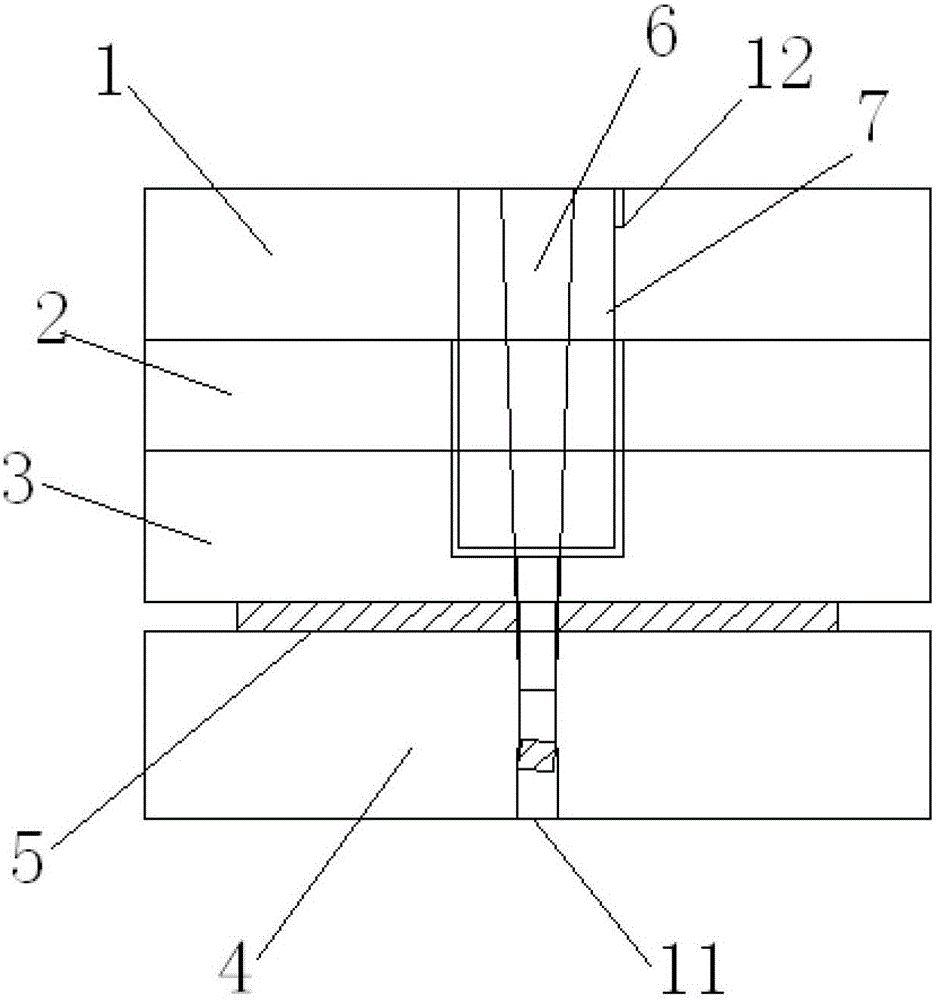
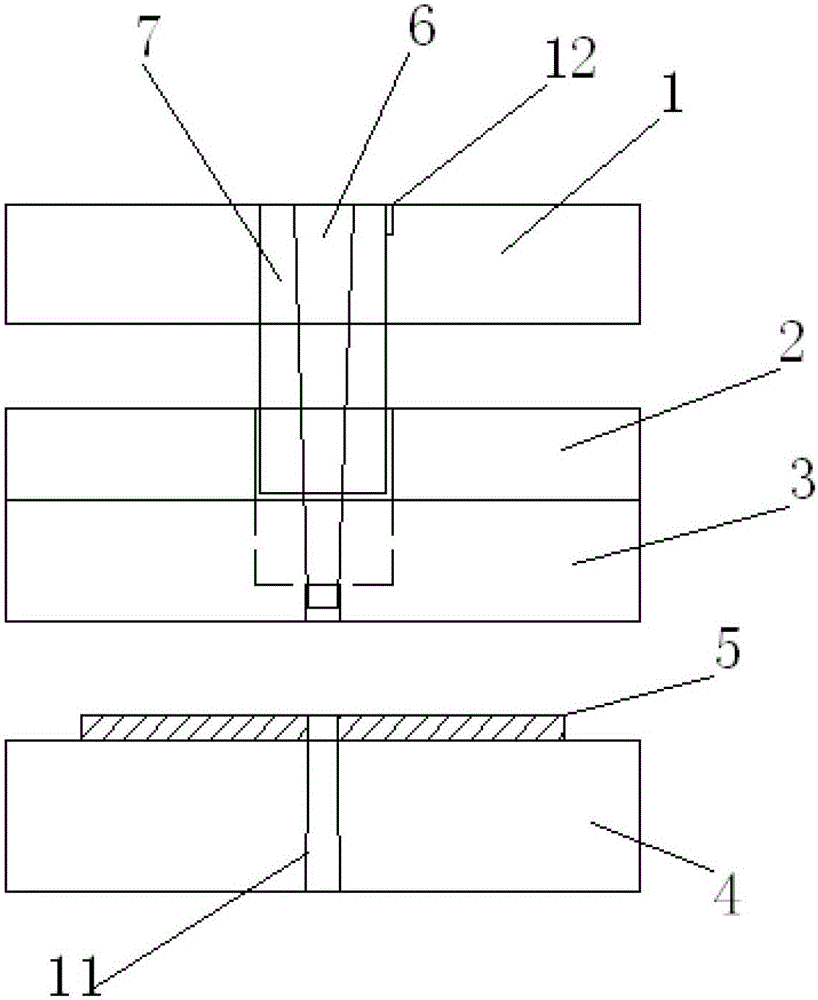
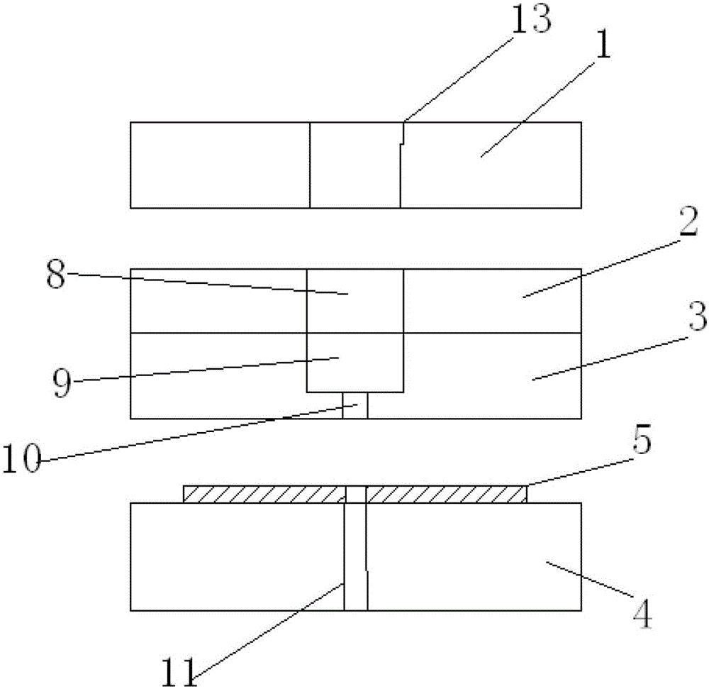
[0022] like figure 1 , figure 2 and image 3 As shown, a special-shaped small punching punch anti-break punching die includes an upper die and a lower die, and the upper die includes an upper clamping plate 1, a stopper plate 2 and a stripper plate 3 positioned in sequence, and the There is an elastic space between the upper splint and the stop plate; the lower mold includes a lower template 4, and the product 5 to be punched is arranged between the stripper plate and the lower template, and an inverted cone The shaped punch 6 and the axial sleeve are set on the sheath 7 outside the punch, corresponding to the sheath, the stopper plate is provided with a first through hole 8, and the stripper plate is provided with The relief hole 9, the sheath is fixed on the upper splint, and extends through the first through hole into the relief hole, corresponding to the punch, the stripping plate is provided with There is a second via hole 10, and a third via hole 11 is provided on th...


PUM


Abstract

The invention discloses an anti-pull-cut punching die with a deformed small punching head. The punching die comprises an upper die and a lower die, wherein the upper die comprises an upper clamping plate, a stop plate and a stripper plate which are positioned in sequence, and an elastic space is formed between the upper clamping plate and the stop plate; the lower die comprises a lower die plate, a product to be punched is arranged between the stripper plate and the lower die plate, the punching head in the shape of an inverted frustum and a protection sleeve positioned outside the punching head in an axial sleeving manner are additionally arranged, a first via hole is formed in the stop plate in correspondence to the protection sleeve, a place reserving hole is formed in the stripper plate, the protection sleeve is fixedly arranged on the upper clamping plate and penetrates through the first via hole to extend into the place reserving hole, a second via hole is formed in the stripper plate in correspondence to the punching head, a third via hole is formed in the lower die plate, and the punching head penetrates through the second via hole. According to the punching die, the pull-cut damage of the punching head can be effectively reduced, the die repair time is shortened, the safety of the die is guaranteed, the production efficiency is improved, the production stability is ensured, the additional waste of product production is avoided, and the purpose of reducing the production cost of the product is achieved.

Description

technical field [0001] The invention relates to a punching die, in particular to a break-proof punching die for small special-shaped punching heads. Background technique [0002] SECC is the English abbreviation of electrolytic sub-lead galvanized steel sheet. It is a stamping material, which is to coat the surface of cold-rolled sheet with a zinc layer. The general thickness of SECC is 0.4-3.2m. Due to its anti-rust and corrosion-resistant properties, it is currently widely used in the fields of automobiles, household appliances, office machines, construction, and production machinery. Due to the needs of the application, it is often necessary to punch special-shaped small punching holes on the SECC sheet through a punching die. In the prior art, when the punching die is punching a small hole, there is a problem that the punch is easily broken. In order to prevent the punch from being broken, a method of setting a sheath outside the punch to prevent it from breaking is usu...

Claims


Application Information

Patent Timeline
Patent Type & Authority Patents(China)
IPC IPC(8): B21D28/34
CPCB21D28/34
Inventor 韦仕拼
Owner JIANGSU BOJUN IND TECH
Learn More