Delay time measuring circuit for optical fiber delay line

A fiber optic delay line and delay time technology, applied in the field of fiber optics, can solve the problems of low measurement accuracy and achieve the effects of high measurement accuracy, low power consumption, and high measurement refresh rate

Inactive Publication Date: 2015-03-25
NO 34 RES INST OF CHINA ELECTRONICS TECH GRP +2
View PDF6 Cites 7 Cited by
  • Summary
  • Abstract
  • Description
  • Claims
  • Application Information

AI Technical Summary

Problems solved by technology

[0004] Although there are many methods for measuring the delay time of optical fiber delay lines at present, the measurement accuracy is not high, and the special delay time measuring instruments for optical fiber delay lines are still in the development stage at home and abroad.

Method used


Image

  • Delay time measuring circuit for optical fiber delay line
  • Delay time measuring circuit for optical fiber delay line
  • Delay time measuring circuit for optical fiber delay line

Examples


Embodiment Construction

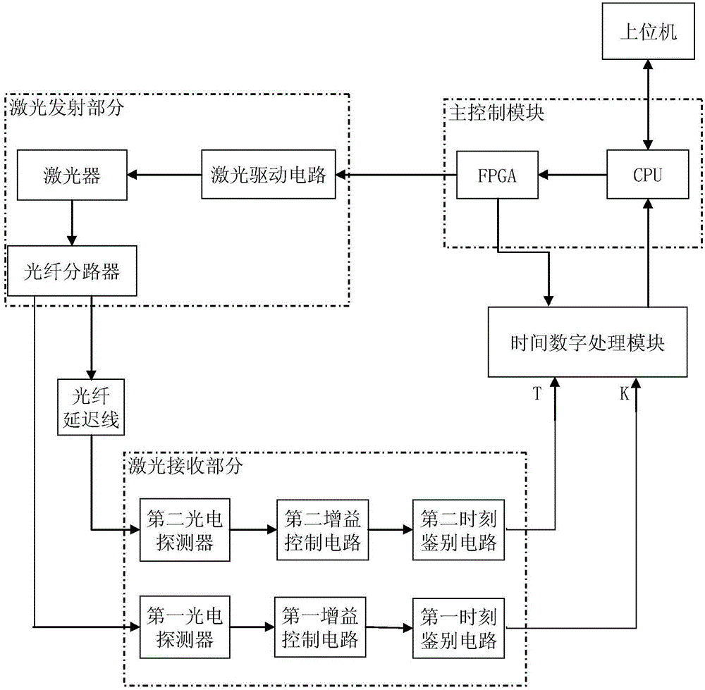
[0024] The embodiment of the delay time measurement circuit of the optical fiber delay line is for example figure 1 As shown, it includes laser pulse transmitting part, laser pulse receiving part, time digital processing module and main control module.

[0025] In this example, the main control module includes an interconnected field programmable gate array FPGA and a microprocessor unit MCU. The field programmable gate array is connected with the laser drive circuit to provide pulse signals for it. The field programmable gate array is also a time digital processing module. The time-to-digital conversion chip provides timing signals. The microprocessor unit is connected with the host computer through the USB interface or RS232 interface, accepts the instructions of the host computer and transmits the measurement results to the host computer. The micro-processing unit is connected with the time-to-digital conversion chip through the serial peripheral interface (SPI interface) ...


PUM


Abstract

The invention provides a delay time measuring circuit for an optical fiber delay line. Narrow-pulse lasers emitted by a laser unit of a laser pulse transmitting part are divided into two paths through an optical fiber branching device. A laser pulse receiving part comprises photoelectric detectors, automatic gain control circuits and moment discriminator circuits, wherein the photoelectric detectors, the automatic gain control circuits and the moment discriminator circuits are all arranged in two same sets. One path of lasers directly enter the first photoelectric detector, and the other path of narrow-pulse lasers enter the second photoelectric detector through the optical fiber delay line to be measured. Two paths of converted electric signals are connected to the corresponding moment discriminator circuits through the corresponding automatic gain control circuits respectively. Output of the first moment discriminator circuit and output of the second moment discriminator circuit are connected to a start channel and a stop channel of a time digital processing module respectively, and the output of the second moment discriminator circuit is connected to a master control module connected with an upper computer. The time different between the timing start signals and the timing termination signals is acquired through the digital processing module, the timing start signals and the timing termination signals are converted into digital signals, the digital signals are transmitted to the upper computer to be displayed through the master control module, and a measurement result is output. By the adoption of the delay time measuring circuit, picosecond-level delay time measurement is achieved, accuracy and the refresh rate are high, and implementation is easy.

Description

technical field [0001] The invention relates to the field of optical fiber technology, in particular to a delay time measuring circuit of an optical fiber delay line based on a time-to-digital converter chip. Background technique [0002] With the continuous development of optical fiber technology, the optical fiber delay line as a new signal processing device is being widely used. The principle of the optical fiber delay line is that the radio frequency electrical signal is converted into the optical signal modulated by the signal and then sent into the optical fiber, and then the radio frequency modulated optical signal is converted into the original radio frequency electrical signal. The RF signal is stored instantaneously in the fiber delay line, and the delay time is proportional to the length of the fiber. [0003] Optical fiber delay lines can realize signal encoding and buffering in optical fiber communication systems, participate in the acquisition and transmission...

Claims


Application Information

Patent Timeline
Patent Type & Authority Applications(China)
IPC IPC(8): G01M11/02
Inventor 黄涌刘武黎志刚李栋李云燕钟昌锦
Owner NO 34 RES INST OF CHINA ELECTRONICS TECH GRP
Why Eureka
Try Eureka