

Power Supply Device and Luminair
A power supply device and voltage source technology, applied in lighting devices, electric light sources, electroluminescent light sources, etc., can solve problems such as rectifier damage, power switch contact welding, etc., and achieve the effect of preventing inrush current.
- Summary
- Abstract
- Description
- Claims
- Application Information
AI Technical Summary
Problems solved by technology
Method used
Image


Examples
no. 1 approach
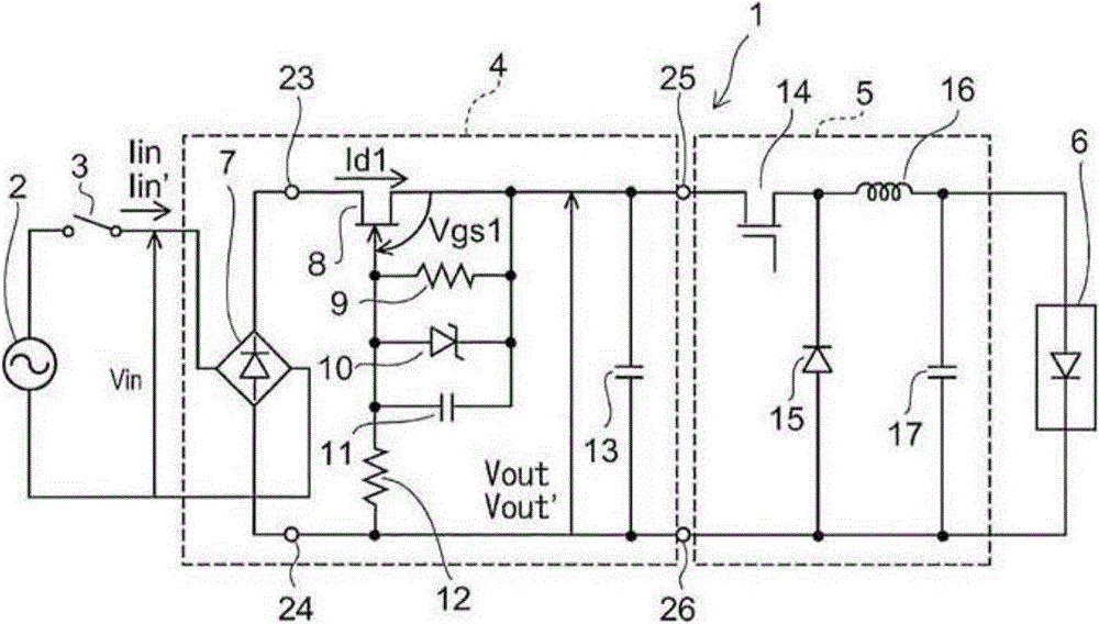
[0057] figure 1 It is a circuit diagram illustrating an illumination device including the power supply device of the first embodiment.
[0058] The lighting device 1 includes a power supply device 4 , a DC-DC converter 5 , and a lighting load 6 .
[0059] The power supply device 4 rectifies and smoothes the AC power supply voltage input through the power switch 3 . The DC-DC converter 5 converts the output of the power supply device 4 into a required voltage, and supplies it to the lighting load 6 .
[0060] The lighting load 6 has, for example, lighting light sources such as light emitting diodes (LEDs). The AC power supply 2 is, for example, a commercial power supply.
[0061] The power supply device 4 includes a rectifier 7 , a normally-on transistor 8 , a smoothing capacitor 13 , a resistor 9 , a resistor 12 , a constant-voltage diode 10 , and a capacitor 11 . The rectifier is, for example, a diode bridge rectifier. The normally-on transistor is a high electron mobili...
no. 2 approach
[0079] A second embodiment will be described.
[0080] Figure 4 It is a circuit diagram illustrating an illumination device including the power supply device of the second embodiment.
[0081] Figure 4 The lighting device 18 includes a power supply device 19 , a DC-DC converter 5 , and a lighting load 6 .
[0082] The power supply device 19 includes a rectifier 7 , a normally-on transistor 8 , and a smoothing capacitor 13 .
[0083] The drain of the normally-on transistor 8 is connected to the high-potential output terminal 23 of the rectifier 7 , and the source of the normally-on transistor 8 is connected to one end of the smoothing capacitor 13 . The other end of the smoothing capacitor 13 is connected to the low potential output terminal 24 of the rectifier 7 . The gate of the normally-on transistor 8 is connected to the source of the normally-on transistor 8 . The output of the power supply unit 4 is taken out from both ends of the smoothing capacitor 13 .
[0084]...
no. 3 approach
[0088] A third embodiment will be described.
[0089] Figure 5 It is a circuit diagram illustrating an illumination device including the power supply device of the third embodiment.
[0090] Figure 5 The lighting device 20 includes a power supply device 21 , a DC-DC converter 5 , and a lighting load 6 .
[0091] The power supply device 21 includes a rectifier 7 , a normally-on transistor 8 , a smoothing capacitor 13 , and an overvoltage protection element 22 .
[0092] The drain of the normally-on transistor 8 is connected to the high-potential output terminal 23 of the rectifier 7 , and the source of the normally-on transistor 8 is connected to one end of the smoothing capacitor 13 . The other end of the smoothing capacitor 13 is connected to the low potential output terminal 24 of the rectifier 7 . The gate of the normally-on transistor 8 is connected to the source of the normally-on transistor 8 . The overvoltage protection element 22 is connected between the drain a...
PUM
 Abstract
Description
Claims
Application Information