

Control Apparatus For Linear Compressor
- Summary
- Abstract
- Description
- Claims
- Application Information
AI Technical Summary
Benefits of technology
Problems solved by technology
Method used
Image

Examples
first embodiment
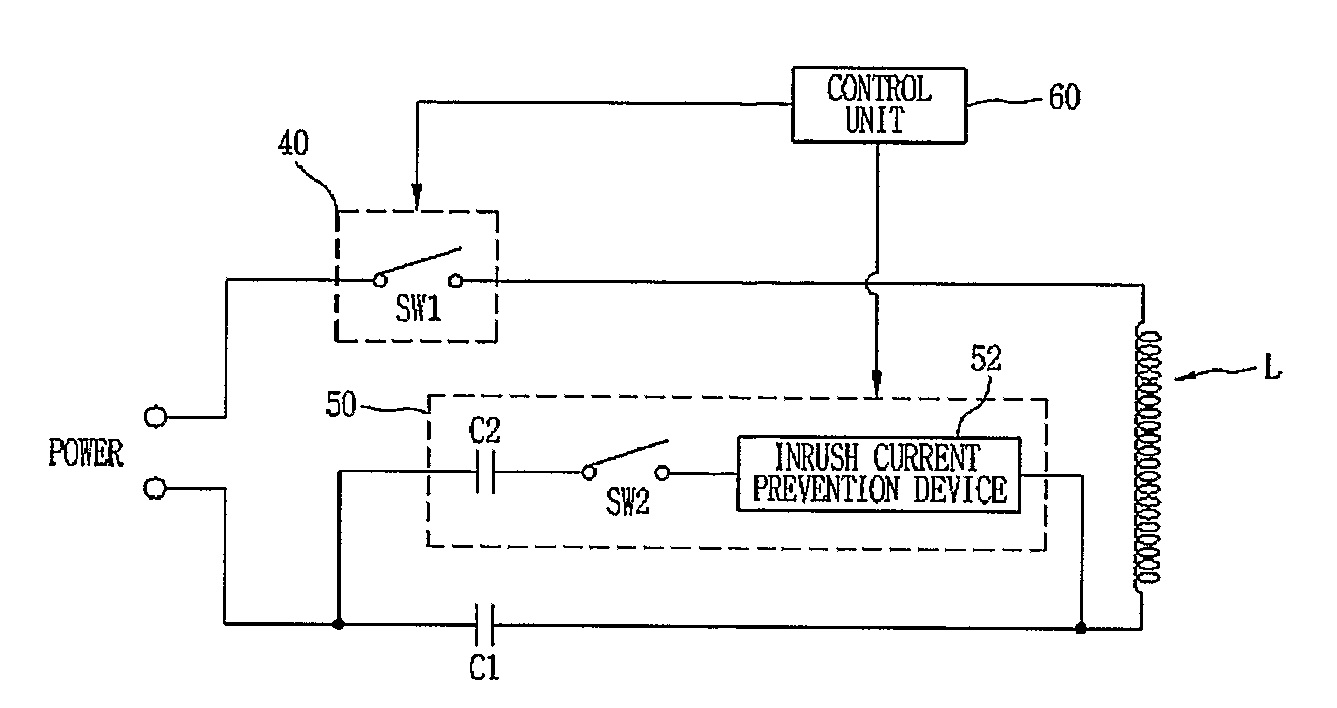
[0061]FIG. 3 is a circuit view illustrating a control apparatus for a linear compressor in accordance with the present invention.
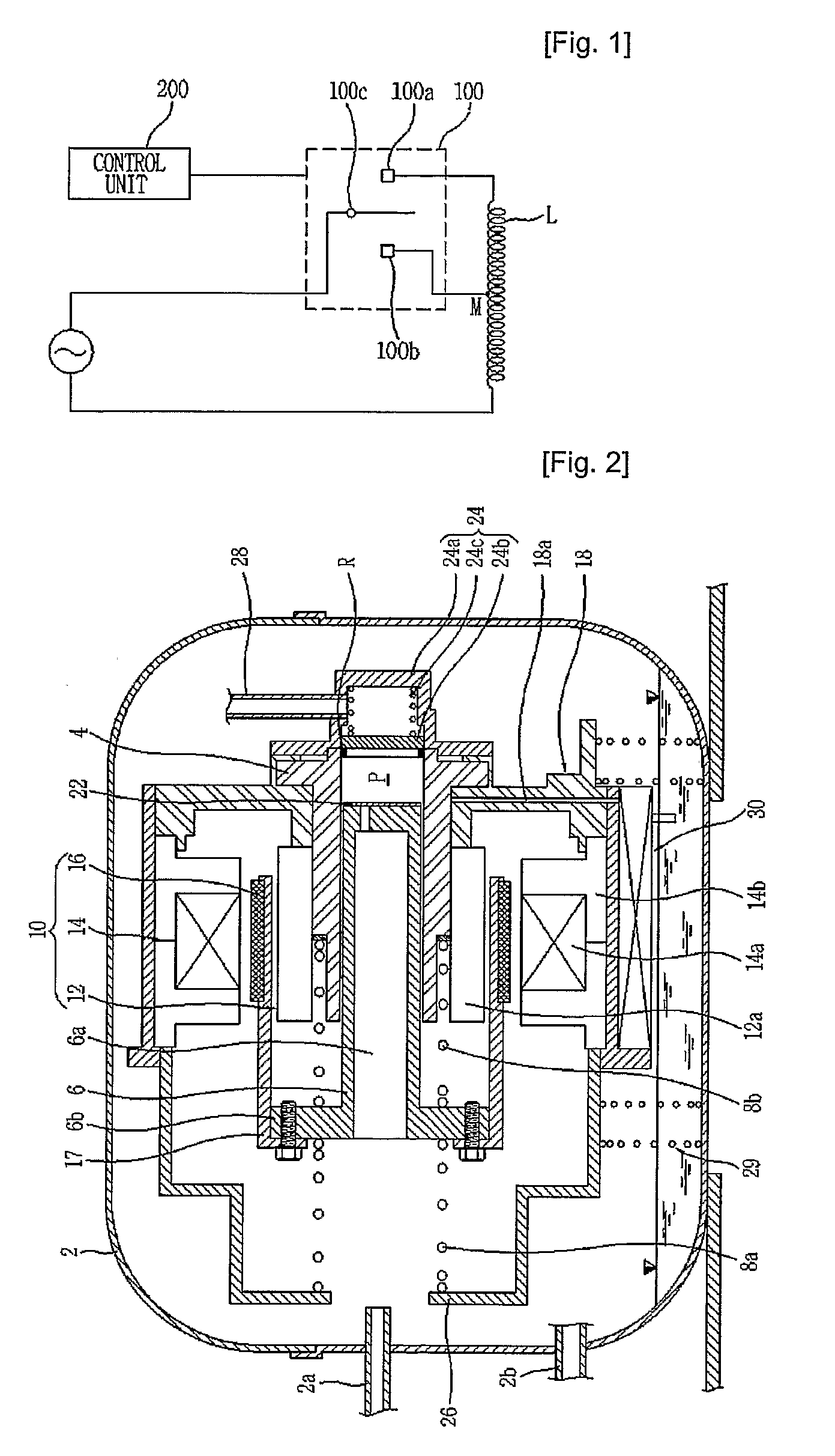
[0062]Still referring to FIG. 2, the linear motor 10 includes an inner stator 12 formed by laminating a plurality of laminations 12a in the circumferential direction, and fixed to the outer portion of the cylinder 4 by the frame 18, an outer stator 14 formed by laminating a plurality of laminations 14b in the circumferential direction around a coil winding body 14a formed by winding a coil, and installed at the outer portion of the cylinder 4 by the frame 18 with a predetermined gap from the inner stator 12, and a permanent magnet 16 disposed at the gap between the inner stator 12 and the outer stator 14, and connected to the piston 6 by the connection member 17. The coil winding body 14a can be fixed to the outer portion of the inner stator 12.
[0063]As shown in FIG. 3, the control apparatus for the linear compressor includes an on / off switch SW140 for rec...
second embodiment
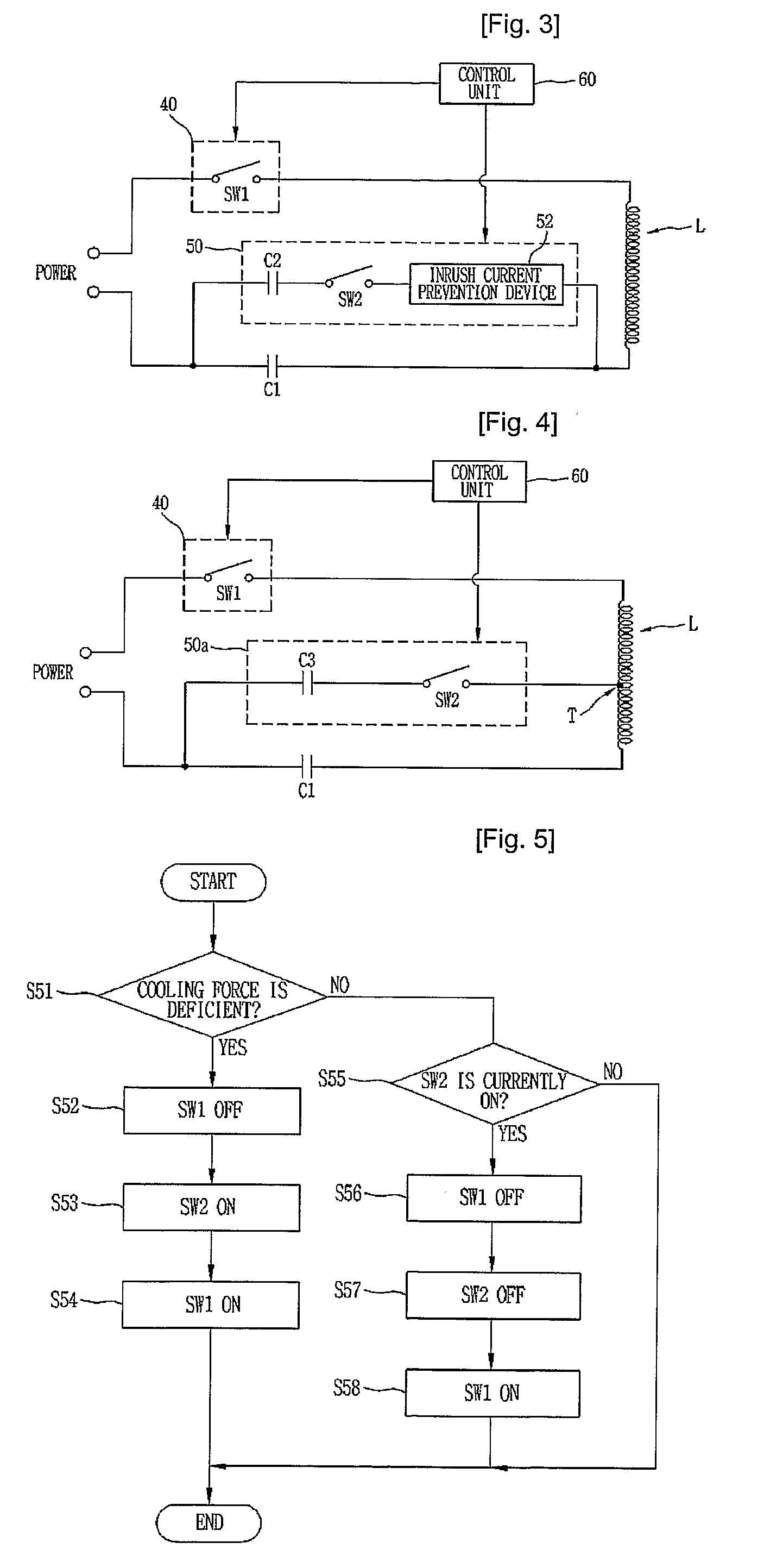
[0070]FIG. 4 is a circuit view illustrating a control apparatus for a linear compressor in accordance with the present invention.
[0071]As depicted in FIG. 4, the control apparatus for the linear compressor includes an on / off switch SW140 for receiving power and supplying power to the linear motor 10, a oil winding body L (identical to the coil winding body 14a of FIG. 2) wound in the circumferential direction of the linear compressor, a capacitor C1 connected in series to the coil winding body L, a capacitance varying unit 50a having one end connected to one end of the capacitor C1 and the other end connected to a winding tap T of the coil winding body L, the capacitance varying unit 50a being connected in parallel to the capacitor C1, and a control unit 60 for controlling the capacitance varying unit 50a to change an output of the linear compressor.
[0072]Here, the on / off switch SW140, the coil winding body L and the capacitor C1 of FIG. 4 are identical to those of FIG. 3 with the s...
PUM
 Abstract
Description
Claims
Application Information