Eureka AIR delivers breakthrough ideas for toughest innovation challenges, trusted by R&D personnel around the world.

Magnetic resonance antenna

a magnetic resonance antenna and antenna technology, applied in the field of magnetic resonance antennas, can solve the problems of incomplete blocking of switching lines, unnecessary and expensive installation of a number of direct current lines within the resonant structure, etc., and achieve the effect of simple, cost-effective and interference-insusceptibl

Active Publication Date: 2005-09-13
SIEMENS HEALTHCARE GMBH
View PDF6 Cites 74 Cited by
  • Summary
  • Abstract
  • Description
  • Claims
  • Application Information

AI Technical Summary

Benefits of technology

[0011]An object of the present invention to provide a magnetic resonance antenna having a birdcage structure which can be detuned with lower switching voltages in an optimally simple, cost-effective and interference-insusceptible assembly by interruption of the longitudinal inductances. A further object is to provide a method to detune the eigen-resonance frequency of such an antenna.
[0014]The radio-frequency switching elements thus can be switched via these common switching lines, such that an elaborate (and thus expensive) installation of a number of direct current lines within the resonant structure is unnecessary. In addition, the possible influence by the direct current lines on the structure is significantly reduced. Since in this assembly all radio-frequency switching elements can be connected in parallel with regard to both switching lines, essentially only the blocking voltage required at the radiation detector switching elements needs to be applied to the switching line as a switching voltage. In addition, the failure of one radio-frequency switching element does not lead to a complete blocking of the switching lines.
[0018]In a preferred exemplary embodiment, one or both ring lines are galvanically interrupted at a location where the use of a capacitive element for galvanic interruption of the ring line is suitable, such that the ring line is closed with regard to radio-frequency. Such a galvanic interruption of the ring line has the advantage that eddy currents are prevented within the ring line. Given a switching of a gradient coil arranged in the magnetic resonance system, such eddy currents could be induced in the ring line and lead to heating of the ring line. The use of capacitive elements for galvanic interruption of the ring line has the advantage that the ring lines are closed in terms of radio-frequency, and thus asymmetries are prevented in the assembly of the antenna structure.
[0027]Connection of the radio-frequency switching elements with the respective ring line via chokes or other inductive elements has the additional advantage that these inductive elements also serve as protective resistors that provide for a compensation of the diode currents insofar as not all of the radio-frequency switching elements exhibit exactly the same parameters. Alternatively, in principle a connection of the radio-frequency switching elements to the switching lines to compensate the diode currents could also ensue via elements acting other than as ohmic resistors.
[0029]Additionally, in order to prevent radio-frequency interferences from being introduced in the birdcage structure from the outside via the switching lines, the switching lines preferably are provided with a suitable low-pass filter on the input side.

Problems solved by technology

The radio-frequency switching elements thus can be switched via these common switching lines, such that an elaborate (and thus expensive) installation of a number of direct current lines within the resonant structure is unnecessary.
In addition, the failure of one radio-frequency switching element does not lead to a complete blocking of the switching lines.

Method used


Image

  • Magnetic resonance antenna
  • Magnetic resonance antenna
  • Magnetic resonance antenna

Examples


Embodiment Construction

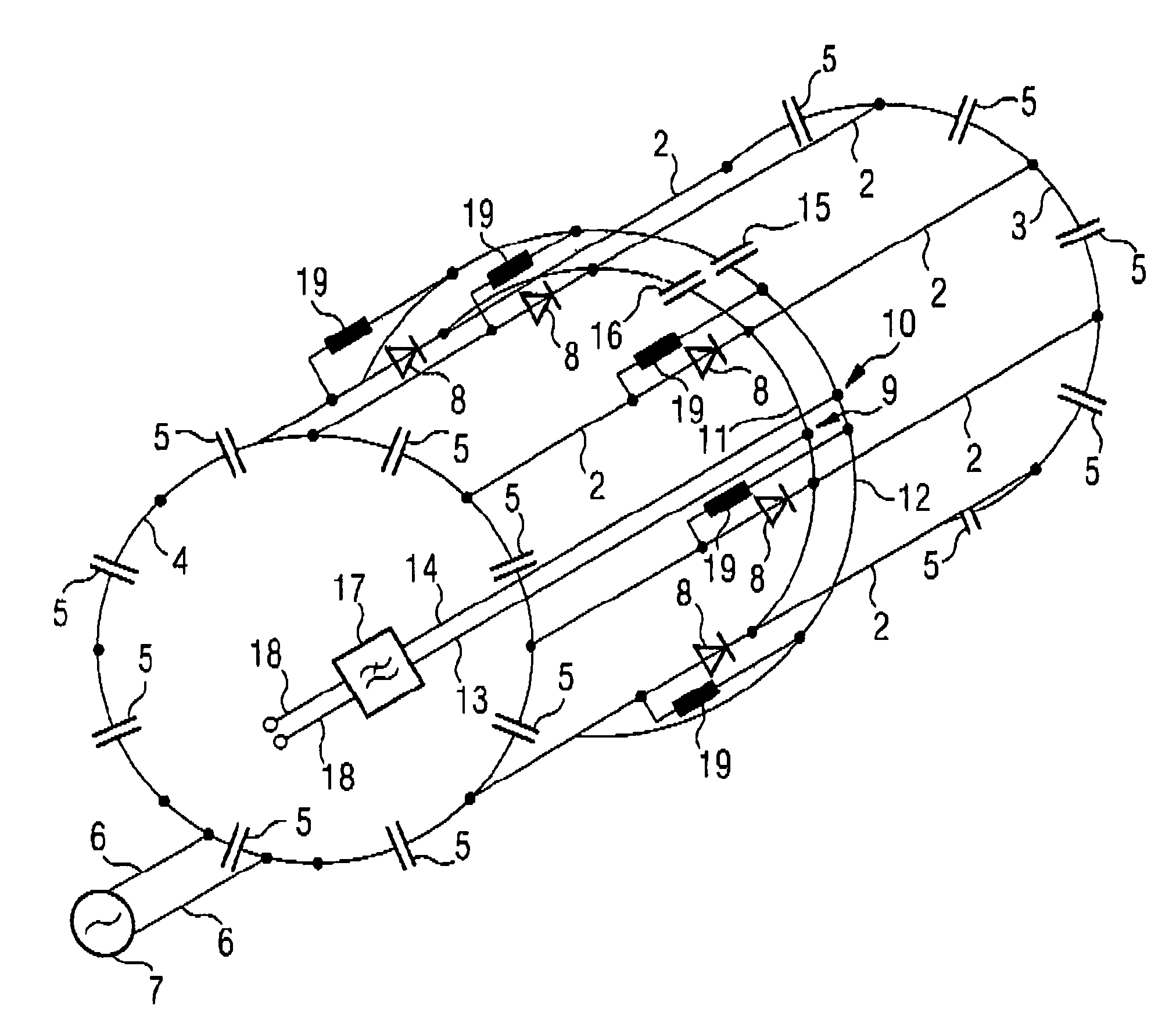
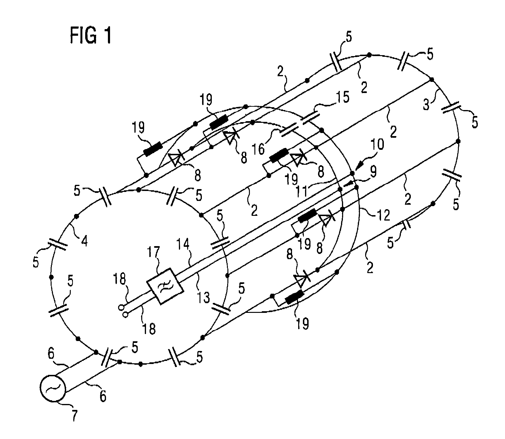
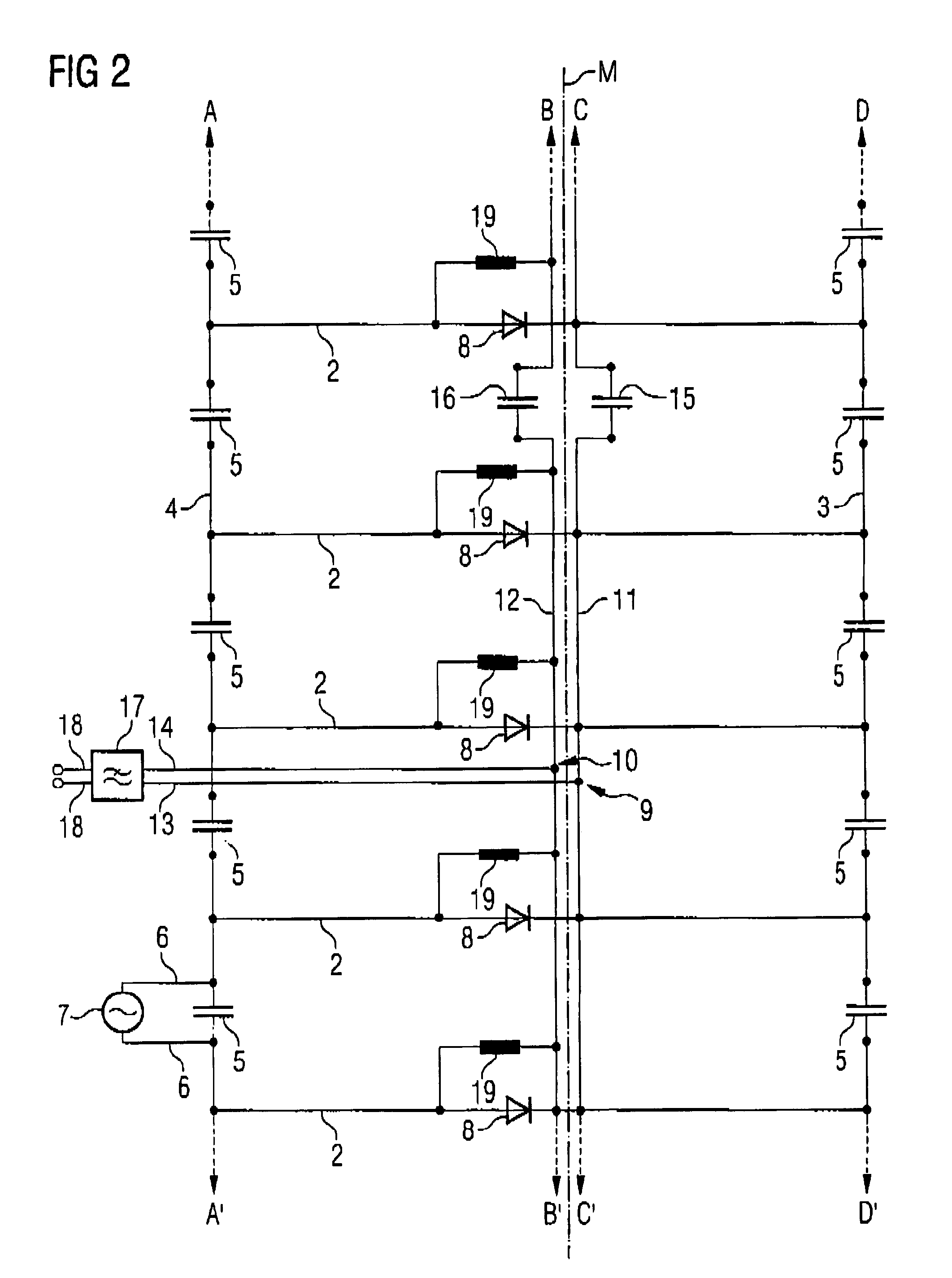
[0037]FIG. 1 shows the typical assembly of a birdcage structure in the form of a simple three-dimensional wire model. Such a birdcage structure is comprised of a number of equidistant longitudinal antenna rods arranged running in parallel on a cylindrical surface. These longitudinal rods are respectively connected among one another in terms of radio-frequency at the ends via antenna ferrules 3, 4. “Connected in terms of radio-frequency” means, in this context, that a galvanic connection is not mandatory, but rather only a connection transparent for radio-frequency currents has to exist. As shown in FIG. 1—as is typically the case in magnetic resonance antennas according to the birdcage structure—resonance capacitors 5 are located in the antenna ferrules, respectively between two connection points of adjacent longitudinal antenna rods 2. For clarity, here all structures are shown only on the outside of an imaginary cylinder around which the wire model extends.

[0038]In the exemplary e...


PUM


Abstract

A magnetic resonance antenna has longitudinal antenna rods in a birdcage structure, and antenna ferrules connecting the longitudinal antenna rods at their ends in terms of radio-frequency. The magnetic resonance antenna has a number of radio-frequency switching elements that interrupt, in terms of radio-frequency, at least one part of the longitudinal antenna rod to detune the eigen-resonance frequency of the antenna with respect to an operating magnetic resonance frequency. For this purpose, the magnetic resonance antenna is provided with two switching lines, directed to the radio-frequency switching elements from outside of the birdcage structure, the switching lines having a ring line connected thereto running annularly on or in the birdcage structure and transverse to the longitudinal antenna rods.

Description

BACKGROUND OF THE INVENTION[0001]1. Field of the Invention[0002]The present invention concerns a magnetic resonance antenna of the type having longitudinal antenna rods disposed in parallel to each other in a birdcage structure, the longitudinal antenna rods being connected in terms of radio-frequency, to a ferrule or ring at each end, and radio-frequency switching elements connected to interrupt. In terms of radio-frequency at least one part of the longitudinal antenna rods to detune the eigen-resonance frequency of the antenna with regard to a working (operating) magnetic resonance frequency.[0003]2. Description of the Prior Art[0004]Modern magnetic resonance systems normally operate with a number of different antennas (also called coils in the following) to emit radio-frequency pulses for magnetic resonance excitation and / or to receive the resulting magnetic resonance signals. A magnetic resonance system typically has a larger coil, known as a whole-body coil, also called a bodyc...

Claims


Application Information

Patent Timeline
Patent Type & Authority Patents(United States)
IPC IPC(8): G01R33/34G01R33/32G01R33/36
CPCG01R33/34046G01R33/3657
Inventor EBERLER, LUDWIGLAZAR, RAZVANNISTLER, JURGENZEBELEIN, GUNTHER
Owner SIEMENS HEALTHCARE GMBH
Why Eureka
Eureka Blog
Learn More