Multi-phase converter

A converter and parallel technology, applied in the direction of instruments, output power conversion devices, conversion equipment with intermediate conversion to AC, etc., can solve the problem of limiting switching frequency, sacrificing power density and dynamic response, and buck regulator efficiency Low and other problems, to achieve the effect of increasing the switching frequency, realizing dynamic fast response, and easy to use

Active Publication Date: 2020-03-24
GOOGLE LLC
View PDF5 Cites 1 Cited by
  • Summary
  • Abstract
  • Description
  • Claims
  • Application Information

AI Technical Summary

Problems solved by technology

In some cases, a large step-down ratio can make the buck regulator inefficient
In addition, the relatively high input voltage limits the switching frequency of the switch, thus sacrificing power density and dynamic response

Method used


Image

  • Multi-phase converter
  • Multi-phase converter
  • Multi-phase converter

Examples


Embodiment Construction

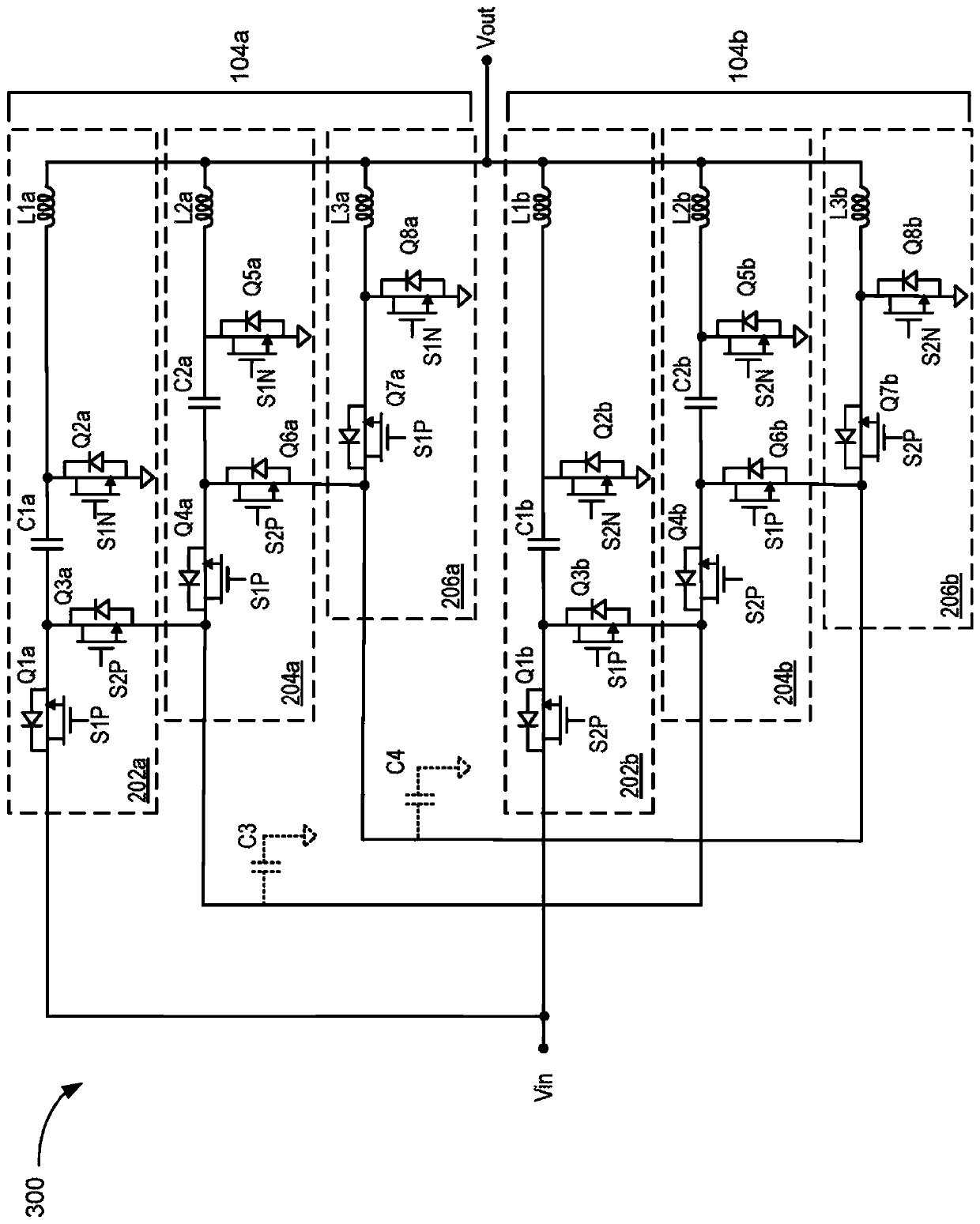
[0013] The subject matter of this written description relates to a capacitor-stacked multi-phase voltage converter that uses capacitors to stack voltages so that MOSFETs operate at smaller switching voltages. Capacitor stack multiphase voltage converters combine the advantages of switched capacitor converters and buck converters. Because the capacitor lowers the switching voltage of the MOSFET, the converter has relatively high efficiency and density compared to converters with higher switching voltages.

[0014] These features and additional features are described in more detail below.

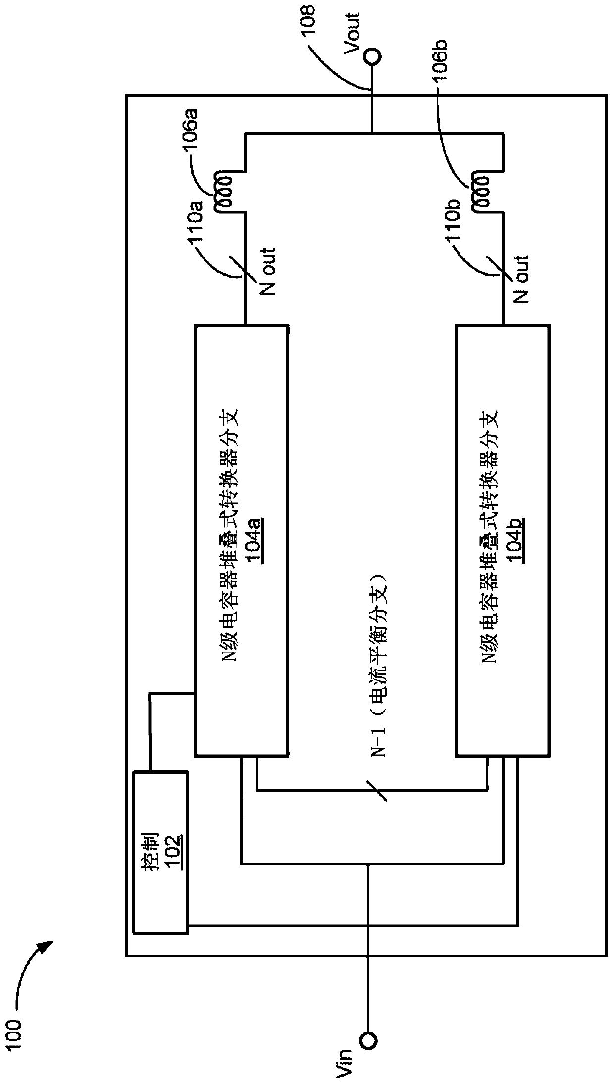
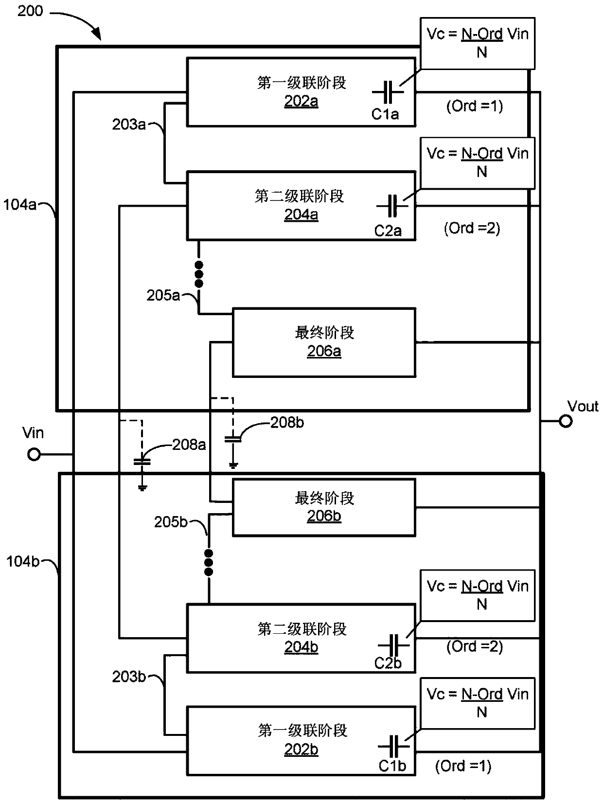
[0015] figure 1 is a block diagram of an example capacitor stacked multiphase voltage converter (CSMPVC). The voltage CSMPVC comprises the control unit 102, at least two N-stage capacitor stack converter parallel branches 104a, 104b. Each parallel converter branch has an input node receiving a direct current (DC) input voltage and N output nodes each outputting a DC output voltage. In som...


PUM


Abstract

An apparatus that includes first and second parallel converter branches, each parallel converter branch including an input node, N output nodes, a plurality of switches, a converter output node, and control logic. The control logic generates a first set of switch signals to control the switches of the first parallel converter branch and a second set of switch signals to control the second parallelconverter branch, the first set switch signals and the second set of switch signals having respective duty cycles to cause each of the first and second parallel converter branches to output the DC output voltage on each of the N output nodes.

Description

Background technique [0001] Multiphase voltage converters for converting a first DC voltage to a second DC voltage can be used in a wide variety of applications. An example is a multiphase buck converter. The output voltage of the multiphase buck converter is lower than the received input voltage. A traditional buck converter includes switches and capacitors, inductors, or both. In some cases, a large step-down ratio can make the buck regulator inefficient. In addition, the relatively high input voltage limits the switching frequency of the switch, thus sacrificing power density and dynamic response. Contents of the invention [0002] In general, an innovative aspect of the subject matter described in this specification can be embodied in a first parallel converter branch and a second parallel converter branch, each parallel converter branch comprising: an input node receiving a direct current (DC) input voltage; N a plurality of output nodes, each of which outputs a DC ...

Claims


Application Information

Patent Timeline
Patent Type & Authority Applications(China)
IPC IPC(8): H02M3/158H02M5/458H02M3/28H02M3/07
CPCH02M3/285H02M5/4585H02M3/1584H02M3/072H02M1/0043H02M7/4837H02M3/1586
Inventor 江帅钟车易李新
Owner GOOGLE LLC
Why Eureka
Try Eureka