Supply voltage decoupling device for HF amplifier circuits

a technology of supply voltage and amplifier circuit, which is applied in the direction of amplifiers, amplifiers with field-effect devices, electric devices, etc., can solve the problems of small power loss due to applied supply voltage, and achieve the effects of avoiding current supply to the amplifier, small power loss, and higher power loss

Inactive Publication Date: 2003-11-25
FRAUNHOFER GESELLSCHAFT ZUR FOERDERUNG DER ANGEWANDTEN FORSCHUNG EV
View PDF6 Cites 76 Cited by
  • Summary
  • Abstract
  • Description
  • Claims
  • Application Information

AI Technical Summary

Benefits of technology

One essential advantage of the present device mainly consists in the fact that the generation of thermal power by means of the d.c. current to be supplied to the amplifiers is avoided. As on that end of the output line of the preferably distributed amplifier, which is not used to carry off the amplified signal, a substantial fraction of the signal power appears only at comparatively low frequencies it is possible that the first elements of the catenary arrangement of subcircuits, which isolate signal components of higher frequencies, are implemented on the amplifier chip because in such a case they produce only a small power loss. Higher power losses are created in the subcircuits joined to the chip, which, due to the small residual bandwidth of the signal to be decoupled from the supply current, can be implemented at a comparatively low expenditure and hence at low costs. On the other hand, the first subcircuits for the absorption of the highest frequency components are integrated into the amplifier chip and can hence be equally implemented at low costs.

Problems solved by technology

Due to the low ohmic resistance of the circuit element the power loss due to the applied supply voltage is only small.

Method used


Image

  • Supply voltage decoupling device for HF amplifier circuits
  • Supply voltage decoupling device for HF amplifier circuits
  • Supply voltage decoupling device for HF amplifier circuits

Examples


Embodiment Construction

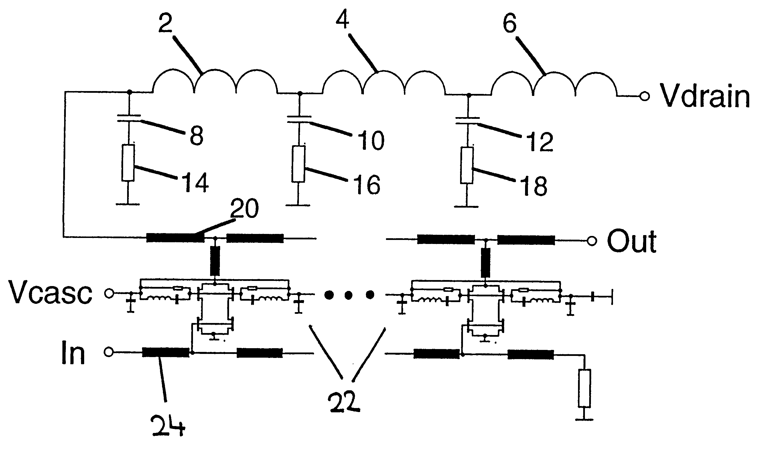
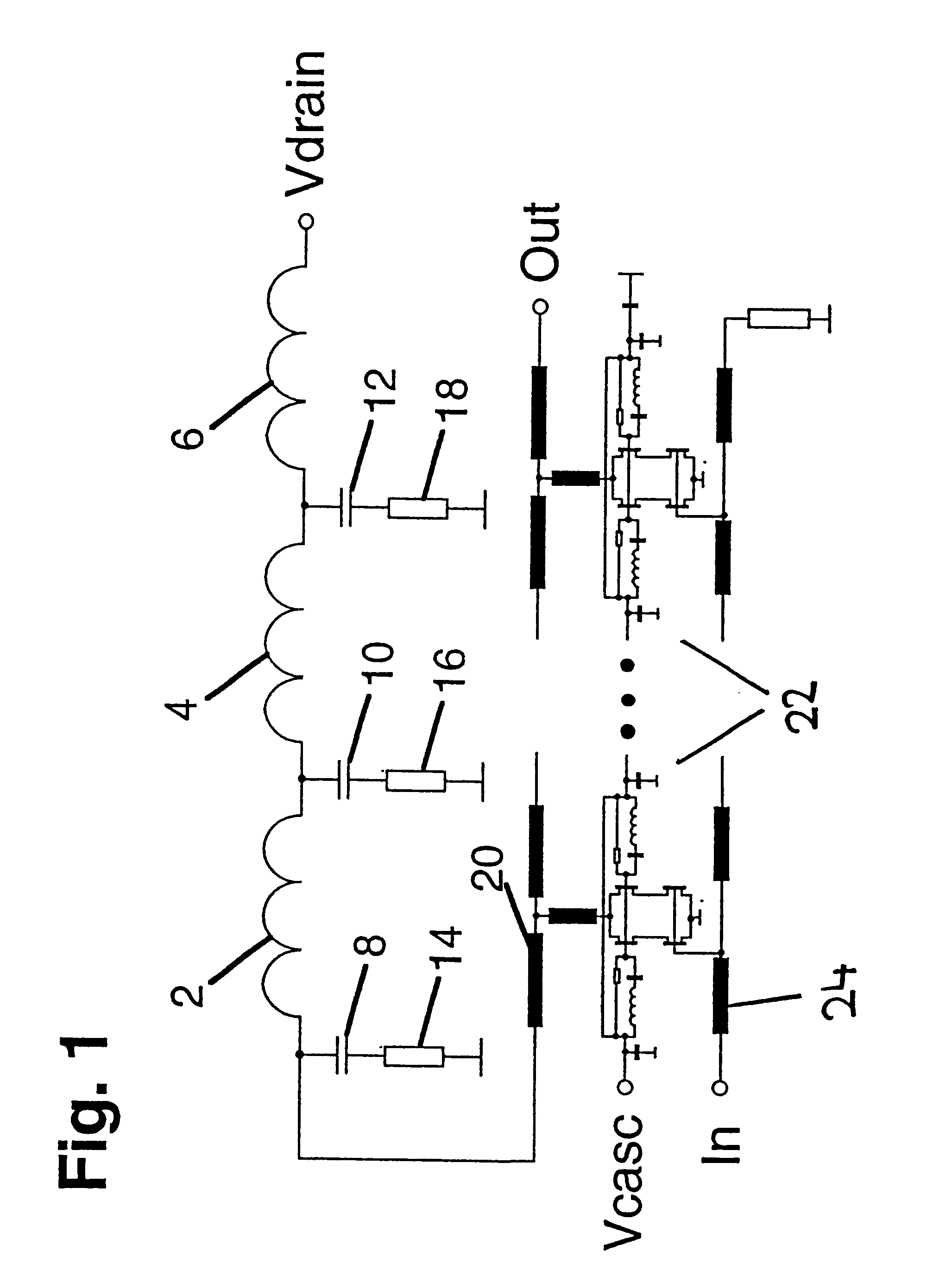
FIG. 1 shows one embodiment of a connection diagram of a distributed amplifier and of the present device for decoupling the supply voltage. The illustrated distributed amplifier is described in more details in the publication by M. Leich et al., "40 GBit / s High Voltage Modulator Driver in P-HEMT Technology", in: Electronics Letters, vol. 35, No. 21, pages 1842 to 1844. Such a distributed amplifier may, for instance, be structured in four sections whereof the figure illustrates only two. This amplifier can be realised in a GaAs P-HEMT-technology and offers a high amplification factor over a wide frequency range. As far as details are concerned reference is made to the aforementioned document.

The distributed amplifier 22 is connected to an output line 20 via which the amplified signals are coupled out at one end (Out). The inventive device is connected to the opposite end of the output line 20, which is not envisaged for coupling out the amplified signals. In the present example, the ...


PUM


Abstract

A device for decoupling a supply voltage for HF amplifier circuits is described which includes an output line for coupling out an amplified signal, wherein one end of the output line, which is not used for coupling out signals, is connected to a circuit element designed as decoupling circuit. The circuit element has a low ohmic d.c. resistance and presents an HF-power absorption capacity that increases as the frequency increases, thus constituting a reflection-free termination for high frequencies. The circuit element is preferably constituted by several discrete subcircuits connected in succession. The device permits the operation of integrated distributed amplifiers of high performance at a low power loss caused by the decoupling circuit.

Description

The present invention relates to a supply voltage decoupling device for HF amplifier circuits, comprising an output line for the output of an amplified signal, wherein one end of the output line, which is not used for signal output, is connected to a circuit element designed as decoupling circuit.The device is provided in particular for very broad band distributed amplifiers, such as those employed in the optical communication technology. For the utilisation of its high potential in terms of transmission bandwidth, the optical communication technology requires electronic amplifier circuits capable of coping even with waves in the millimeter range while starting out from frequencies in the audible range. This requires a bandwidth in amplification that ranges from a few kHz up to a few tens of GHz.For the operation of the employed amplifier circuits decoupling of the DC voltage from the signal-carrying part of the circuit is necessary, specifically in the manner provided by the presen...

Claims


Application Information

Patent Timeline
Patent Type & Authority Patents(United States)
IPC IPC(8): H03F3/60
CPCH03F1/30H03F3/607H03F2200/15
Inventor LEICH, MARTINSCHLECTWEG, MICHAEL
Owner FRAUNHOFER GESELLSCHAFT ZUR FOERDERUNG DER ANGEWANDTEN FORSCHUNG EV
Why Eureka
Try Eureka