

Switching voltage regulator operating without a discontinuous mode
a voltage regulator and discontinuous mode technology, applied in the direction of dc-dc conversion, climate sustainability, power conversion systems, etc., can solve the problems of reducing power delivery efficiency and unfavorable high-frequency noise, and achieve the effect of avoiding drawbacks
- Summary
- Abstract
- Description
- Claims
- Application Information
AI Technical Summary
Benefits of technology
Problems solved by technology
Method used
Image

Examples
Embodiment Construction
[0021] The preferred embodiments according to the present invention will be described in detail with reference to the drawings.
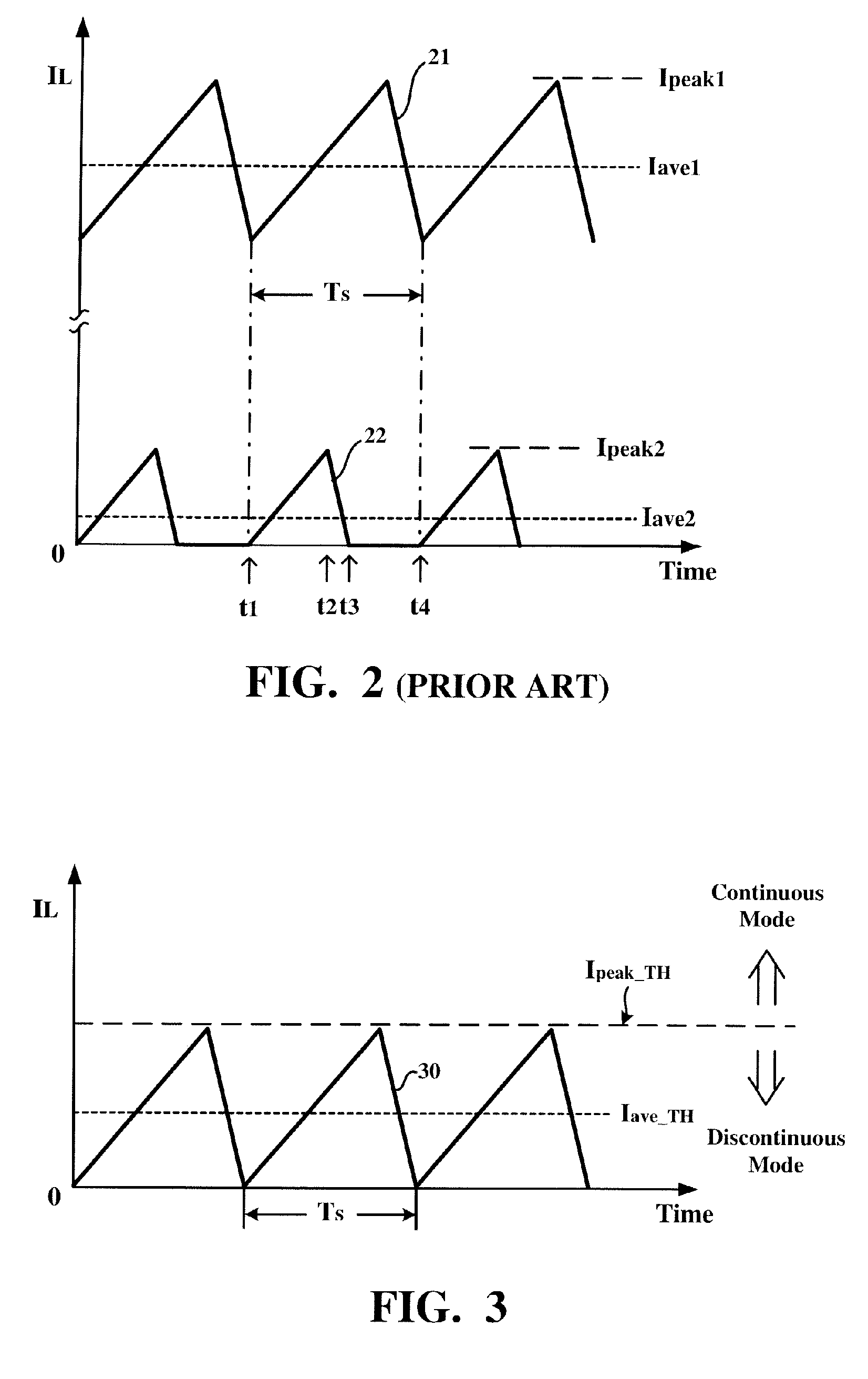
[0022] It is observed from FIG. 2 that the relationship between the peak current and the average current flowing through the inductor presents an essential difference between the continuous and discontinuous modes. More specifically, in the continuous mode indicated by the curve 21, the average current Iave1 flowing through the inductor L is higher than half the peak current Ipeak1 flowing through the inductor L. However, in the discontinuous mode indicated by the curve 22, the average current Iave2 flowing through the inductor L is lower than half the peak current Ipeak2 flowing through the inductor L because during one part of each switch period TS the inductor current IL is substantially equal to zero given that a current reversal preventing device is provided. Therefore, in order to avoid the discontinuous mode, half the peak current flowing through the...
PUM
 Abstract
Description
Claims
Application Information