
Instruments for Setting Acetabular Cup

Active Publication Date: 2008-03-27
GRADEL SA
View PDF15 Cites 155 Cited by
  • Summary
  • Abstract
  • Description
  • Claims
  • Application Information

AI Technical Summary

Benefits of technology

[0019]The problem addressed by the present invention is to avoid the drawbacks of known acetabular cup prosthesis setting instruments by proposing a new instrument structure that combines mechanically strong retention of the cup on an impactor for manipulating the cup and setting it in an acetabular cavity and total absence of deformation or deterioration of the concave distal face of the cup by the instruments.
[0020]With the means according to the invention, it must be possible to impact the cup into the acetabular cavity, orient it in a precise and satisfactory way and fix it correctly into the acetabular cavity, without degrading the concave distal sliding surface of the cup and without any excrescence on the external surface of the cup or deterioration of the peripheral area of bone around the cup.

Problems solved by technology

In all cases, one problem is positioning and fixing the metallic cup in the acetabular cavity in the bone.
For example, an instrument able to expand and contract radially and bearing on a plurality of discontinuous areas of the concave distal face of the cup to hold the cup during setting would necessarily cause permanent and localized deformation of the concave distal face of the cup or insufficient retention, and so this way of holding it is not acceptable.
The bearing engagement of the sliding bar locally degrades the sliding face of the cup, which is not acceptable.
The device is complex, necessitating assembly of many parts, with a plurality of gas sealing means, and the document does not mention or solve the problem of deformation of the concave distal face of the cup as a result of unequal bearing stresses.
However, this locally degrades the bone in the retaining area around the cup, which weakens the subsequent retention of the cup in the bone.
This device is complex, consisting of an assembly of a relatively large number of parts, and is not suited to fixing cups that are not undercut.
Moreover, the screwing maneuver induces unwanted torques on the cup, with the risk of degrading the quality of its fixing into the acetabular cavity.
This pierced cup structure is not applicable to a dual mobility prosthesis.
Thus the cup setting instruments known at present do not provide satisfactory retention of the cup for free orientation thereof and sufficient bearing engagement thereof in the bone without degrading the cup or the adjacent bone.
Given that patients come in diverse sizes, the surgeon must necessarily have a relatively large stock of parts, which increases the overall amount tied up in this way.

Method used


Image

  • Instruments for Setting Acetabular Cup
  • Instruments for Setting Acetabular Cup
  • Instruments for Setting Acetabular Cup

Examples


Embodiment Construction

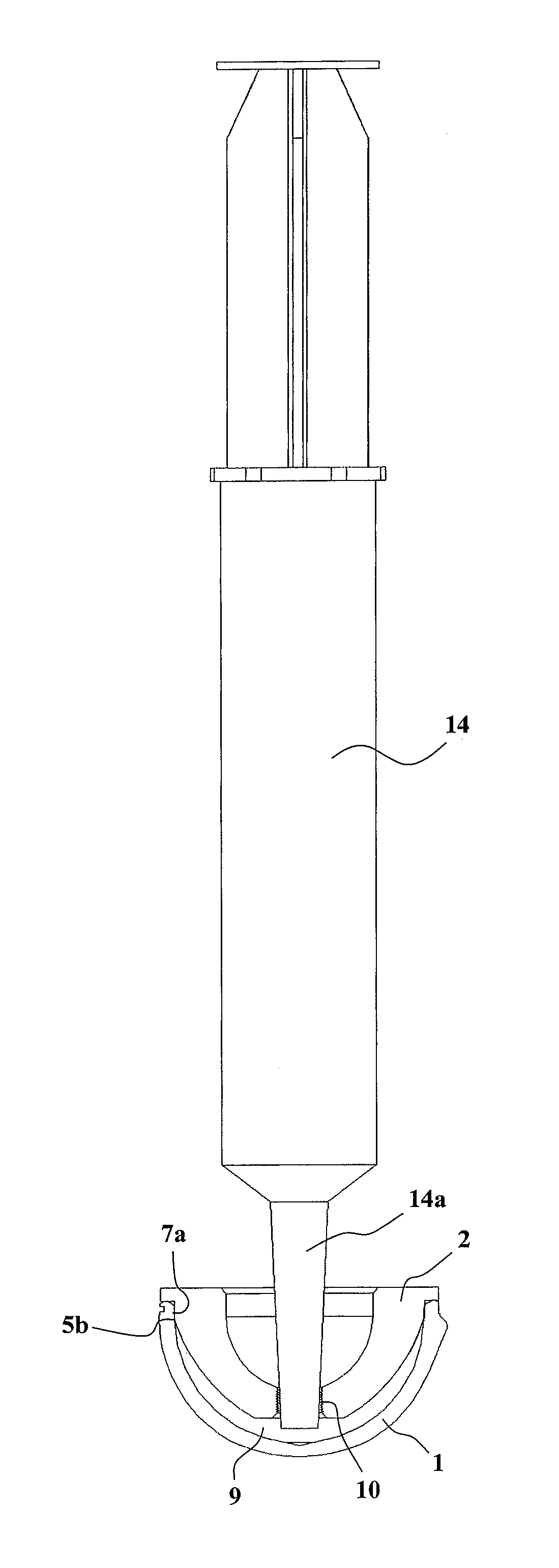
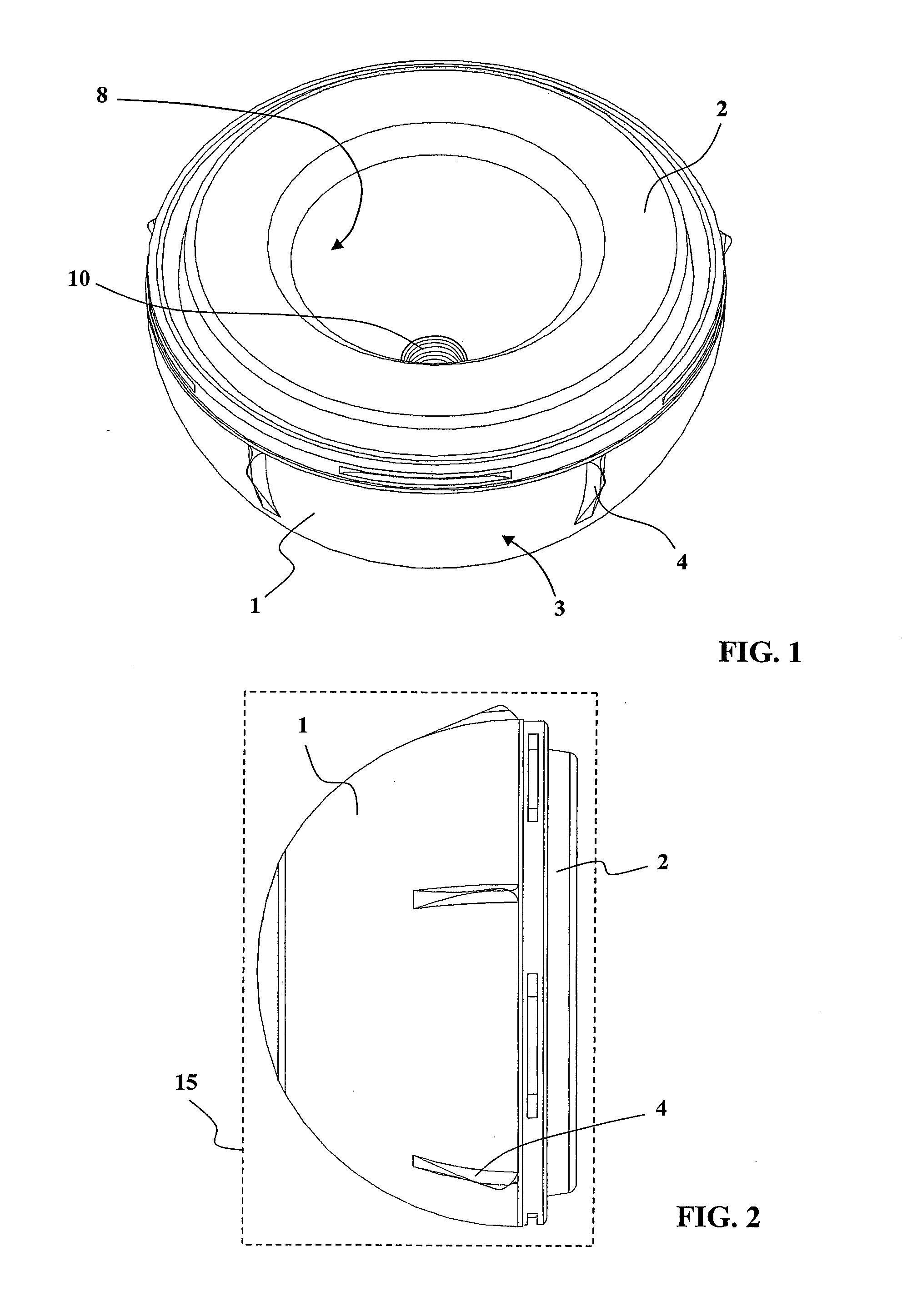
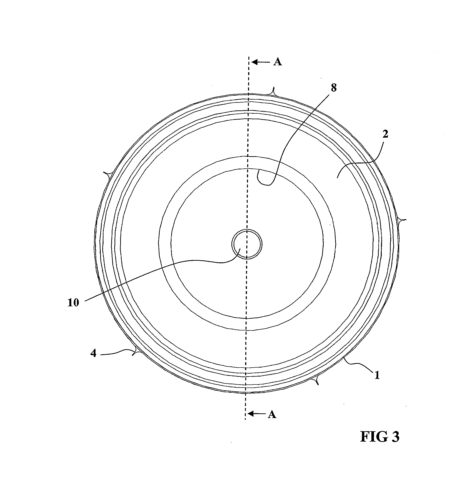
[0061]In the embodiment shown in FIGS. 1 to 4, the acetabular cup prosthesis setting instruments comprise a cup 1 and an adapter 2 conformed as an impaction and temporary trial insert.

[0062]The cup 1 constitutes the permanent cup intended to be fixed into an acetabular cavity in the pelvic bone.

[0063]On the other hand, the adapter 2 has at least the function of an intermediate part between the cup 1 and an impactor that is used to manipulate the cup 1 when setting it in the acetabular cavity, and the adapter 2 is intended then to be replaced by a permanent insert.

[0064]The cup 1 is a hemisphere with a relatively thin wall, having a convex proximal face 3, seen better in FIG. 4, of generally hemispherical shape, optionally with anchoring fins 4, and a concave distal face 5 comprising a hemispherical sliding surface 5a extended by a cylindrical or slightly conical annular retaining surface 5b extending to a peripheral lip 6.

[0065]The hemispherical surface 5a of the cup 1 is perfectly ...


PUM


Abstract

A cup and a temporary insert are respectively configured to be tightly press fitted into each other along their periphery. The temporary insert includes a through hole communicating outside with a free space between the outer surface of the temporary insert and the inner surface of the cup. In the through hole can be engaged the threaded end of an impactor, for manipulating the cup when it is being set. A syringe can be engaged, enabling a liquid under pressure to be injected into the free space, thus separating the temporary insert from the cup without any risk of damaging the inner surface of the cup. Thus, the cup can be securely manipulated when it is being set without any risk of damaging the inner surface of the cup.

Description

TECHNICAL FIELD OF THE INVENTION[0001]The present invention concerns instruments for setting a prosthesic acetabular cup intended to replace the natural acetabular cup of the hip.[0002]A total hip prosthesis comprises two parts constituting a ball-joint, namely a female part intended to replace the natural acetabular cup of the hip and a male part intended to replace the head of the femur.[0003]The male part of the joint generally includes a rod intended to penetrate into the medullary canal of the femur and the proximal end whereof is connected by a neck to a spherical head intended to penetrate into the acetabular cup.[0004]The female part of the joint, which has to replace the natural acetabular cup of the hip, and will be generally referred to as the acetabular cup, usually comprises a hemispherical metallic cup with a convex proximal face and a concave distal face, the convex proximal face being accommodated in a prepared acetabular cavity in the pelvic bone, the concave distal...

Claims


Application Information

Patent Timeline
IPC IPC(8): A61F2/32A61B17/58
CPCA61F2/0095A61F2220/0033A61F2/4609A61F2/4637A61F2/4684A61F2002/30077A61F2002/30354A61F2002/30672A61F2002/3208A61F2002/3404A61F2002/3419A61F2002/4624A61F2002/4629A61F2002/4641A61F2002/4653A61F2002/4681A61F2002/4693A61F2210/0066A61F2/34A61F2/4603A61F2002/3403A61F2002/3417
Inventor GRADEL, THOMAS
Owner GRADEL SA
Learn More