Pulse-width modulation amplifier and suppression of clipping therefor

a pulse-width modulation and amplifier technology, applied in the direction of electrical transducers, transducer casings/cabinets/supports, gain control, etc., can solve the problems of circuit operation being interrupted or become unstable, distortion of output waveforms, and affecting the operation of circuits, so as to reduce power use efficiency, avoid the effect of excessive current, and prevent excessive curren

Active Publication Date: 2006-01-12
YAMAHA CORP
View PDF1 Cites 77 Cited by
  • Summary
  • Abstract
  • Description
  • Claims
  • Application Information

AI Technical Summary

Benefits of technology

[0017] It is an object of the present invention to provide a pulse-width modulation (PWM) amplifier used for the power amplification of audio signals and the like, which can reliably prevent an excessive current from flowing through a switched amplification stage due to operation error caused by noise between positive voltage and negative voltage. Herein, the PWM amplifier has various advantages in which the power source circuit and other circuits are not necessarily increased in scale so as not to reduce the power use efficiency; it is possible to avoid the occurrence of trouble in the decoding operation due to excessive input signal being continued; anti-clipping processing does not interrupt pulse-width modulation, which is thus not interrupted in processing; it is possible to reduce influence on a closed loop, which realizes feedback from the latter stage to the former stage with respect to a PWM circuit, during the anti-clipping processing; hence, it is possible to avoid deterioration of the quality of an output waveform produced by the PWM amplifier.

Problems solved by technology

Conventionally, pulse-width modulation (PWM) effected on large-amplitude signals may cause clipping, which in turn causes partial loss of waveforms (e.g., flattening or partial distortion of waveforms) reproduced based on pulse-width modulated signals.
In the technology disclosed in Japanese Patent No. 3130919, the circuit operation may be interrupted or become unstable when it is switched over into the anti-clipping mode or returned to the normal mode.
This causes distortion of an output waveform.
In the anti-clipping mode, the analog input signal is processed with half of the ‘normal’ source voltage, which may deteriorate noise characteristics.
In particular, these problems may apparently occur when ‘relatively small’ clipping occurs in waveforms.
In addition, the aforementioned technology requires a specially-designed power source circuit, which can produce double voltage that is double the normal voltage produced by the normal power source circuit, which may increase the overall scale of the power source system.
Such a power source circuit providing double voltage is used only in the anti-clipping mode, which certainly reduces the overall power use efficiency.
Such disturbance causes distortion of an output waveform, which apparently appears in the case of relatively small clipping.
When an analog input signal has an excessive amplitude so that positive voltage (or negative voltage) is continuously applied to the circuitry, the capacitor C301 or C302 must be excessively charged, and this causes trouble in the decoding operation.

Method used


Image

  • Pulse-width modulation amplifier and suppression of clipping therefor
  • Pulse-width modulation amplifier and suppression of clipping therefor
  • Pulse-width modulation amplifier and suppression of clipping therefor

Examples


first embodiment

1. First Embodiment

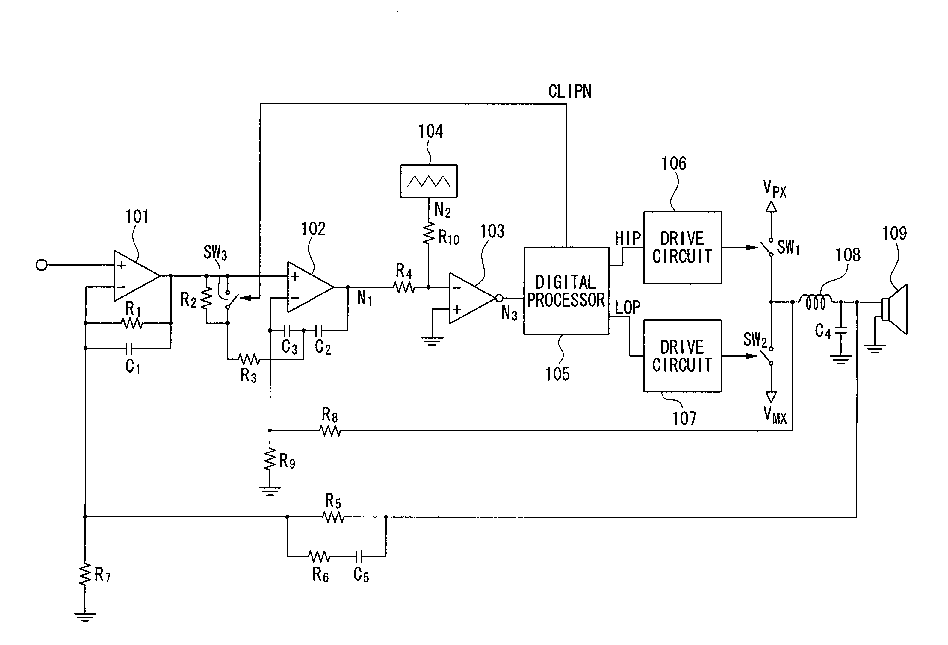
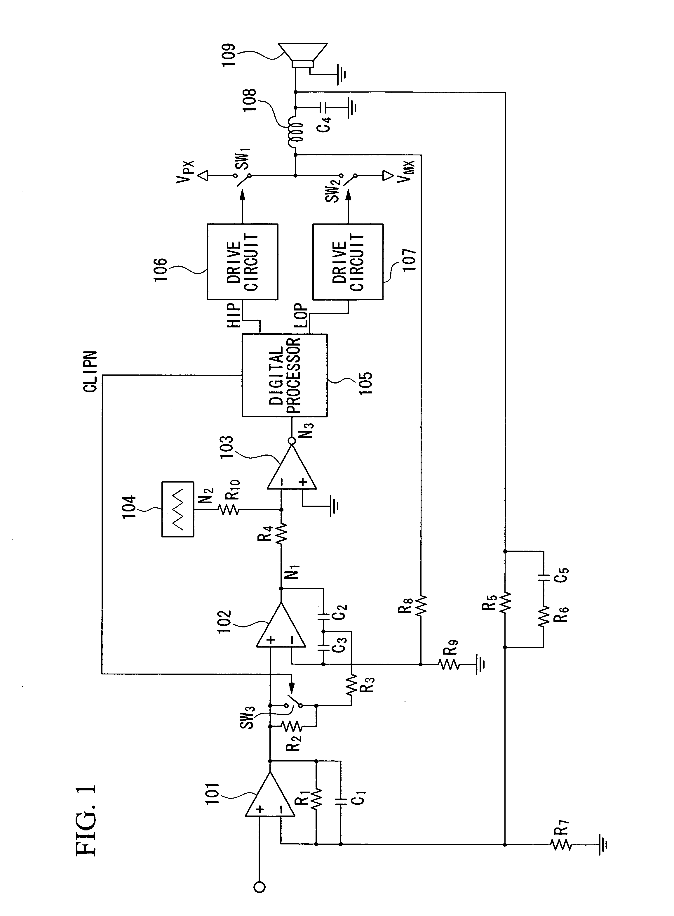
[0044]FIG. 1 is a block diagram showing the overall constitution of a class-D amplifier using pulse-width modulation in accordance with a first embodiment of the invention.

[0045] Reference numeral 101 designates an operational amplifier whose non-inverting input terminal is connected to an input terminal receiving an analog input signal. A resistor R1 is connected between the inverting input terminal and output terminal of the operational amplifier 101. A capacitor C1 is connected between the inverting input terminal and output terminal of the operational amplifier 101.

[0046] Reference numeral 102 designates an operational amplifier whose non-inverting input terminal is connected to the output terminal of the operational amplifier 101. Capacitors C2 and C3 are connected in series and are inserted between the inverting input terminal and output terminal of the operational amplifier 102. A resistor R3 and a switch SW3 are connected in series and are inserted betwe...

second embodiment

2. Second Embodiment

[0074]FIG. 7 is a block diagram showing the overall constitution of a class-D amplifier using pulse-width modulation in accordance with a second embodiment of the invention, wherein parts identical to those shown in FIG. 1 are designated by the same reference numerals; hence, the detailed description thereof will be omitted.

[0075] The second embodiment differs from the first embodiment that the digital processor 105 is replaced with a clipping detection circuit 400, and the PWM signal N3 output from the operational amplifier 103 is directly applied to the switches SW1 and SW2 without the intervention of the drive circuits 106 and 107.

[0076]FIG. 8 is a circuit diagram showing the detailed constitution of the clipping detection circuit 400 shown in FIG. 7. Reference numeral 401 designates an input terminal for inputting a clock pulse signal CK, which is used as a carrier wave for pulse-width modulation and whose frequency matches the frequency of a triangular wav...


PUM


Abstract

A pulse-width modulation (PWM) amplifier is adapted to a class-D amplifier in which an analog input signal is subjected to integration, pulse-width modulation, and switched amplification, wherein a glitch elimination circuit eliminates noise from a pulse-width modulated signal, from which a high pulse signal and a low pulse signal are isolated such that each pulse is delayed by a dead time at the leading-edge timing thereof. When both of them are simultaneously set to a high level, one of them is reduced in level. In response to the occurrence of clipping, an integration constant applied to an operational amplifier is automatically changed from a primary integration constant to a secondary integration constant. When the clipped state is sustained for a prescribed time, an inversion pulse is compulsorily introduced into the pulse-width modulated signal.

Description

BACKGROUND OF THE INVENTION [0001] 1. Field of the Invention [0002] This invention relates to pulse-width modulation (PWM) amplifiers used for power amplification of audio signals, wherein clipping is suppressed so as to avoid deterioration of waveforms. [0003] This application claims priority on Japanese Patent Applications Nos. 2004-197347 and 2004-197385, the contents of which are incorporated herein by reference. [0004] 2. Description of the Related Art [0005] Conventionally, pulse-width modulation (PWM) effected on large-amplitude signals may cause clipping, which in turn causes partial loss of waveforms (e.g., flattening or partial distortion of waveforms) reproduced based on pulse-width modulated signals. Japanese Examined Utility Model Publication No. H04-38566 teaches a technology for the prevention of partial loss of waveforms due to clipping occurring in pulse-width modulation, wherein clipping is canceled by compulsorily introducing pulses upon the detection of a clipped...

Claims


Application Information

Patent Timeline
Patent Type & Authority Applications(United States)
IPC IPC(8): H03G3/00
CPCH03F1/26H03F3/217H03G11/00H03F2200/66H03F2200/03
Inventor TSUJI, NOBUAKI
Owner YAMAHA CORP
Why Eureka
Try Eureka