Current clamping parallel battery charging system to supplement regenerative braking in electric vehicle

a charging system and current clamping technology, applied in battery/fuel cell control arrangement, light to electrical conversion, safety/protection circuit, etc., can solve the problems of high current generation and heat generation of regenerative braking and driving an electric motor, and achieve the effect of simplifying the battery system and the battery system

Inactive Publication Date: 2011-04-21
WARD THOMAS ALLAN
View PDF10 Cites 42 Cited by
  • Summary
  • Abstract
  • Description
  • Claims
  • Application Information

AI Technical Summary

Benefits of technology

[0007]Embodiments of the present invention provide a simple battery system that can be connected to an electric motor powered vehicle when additional battery charge is desired. The battery system is simplified by connecting an additional battery in parallel through a current limiting or clamping circuit so that excessive charge from regenerative braking or operation of the electric motor does not dictate use of a complex cooling system in the additional battery.

Problems solved by technology

Initially, it is recognized that both regenerative braking and driving an electric motor require high currents that generate significant heat requiring a complex battery cooling system.

Method used


Image

  • Current clamping parallel battery charging system to supplement regenerative braking in electric vehicle
  • Current clamping parallel battery charging system to supplement regenerative braking in electric vehicle
  • Current clamping parallel battery charging system to supplement regenerative braking in electric vehicle

Examples


Embodiment Construction

I. Low Current Chargers

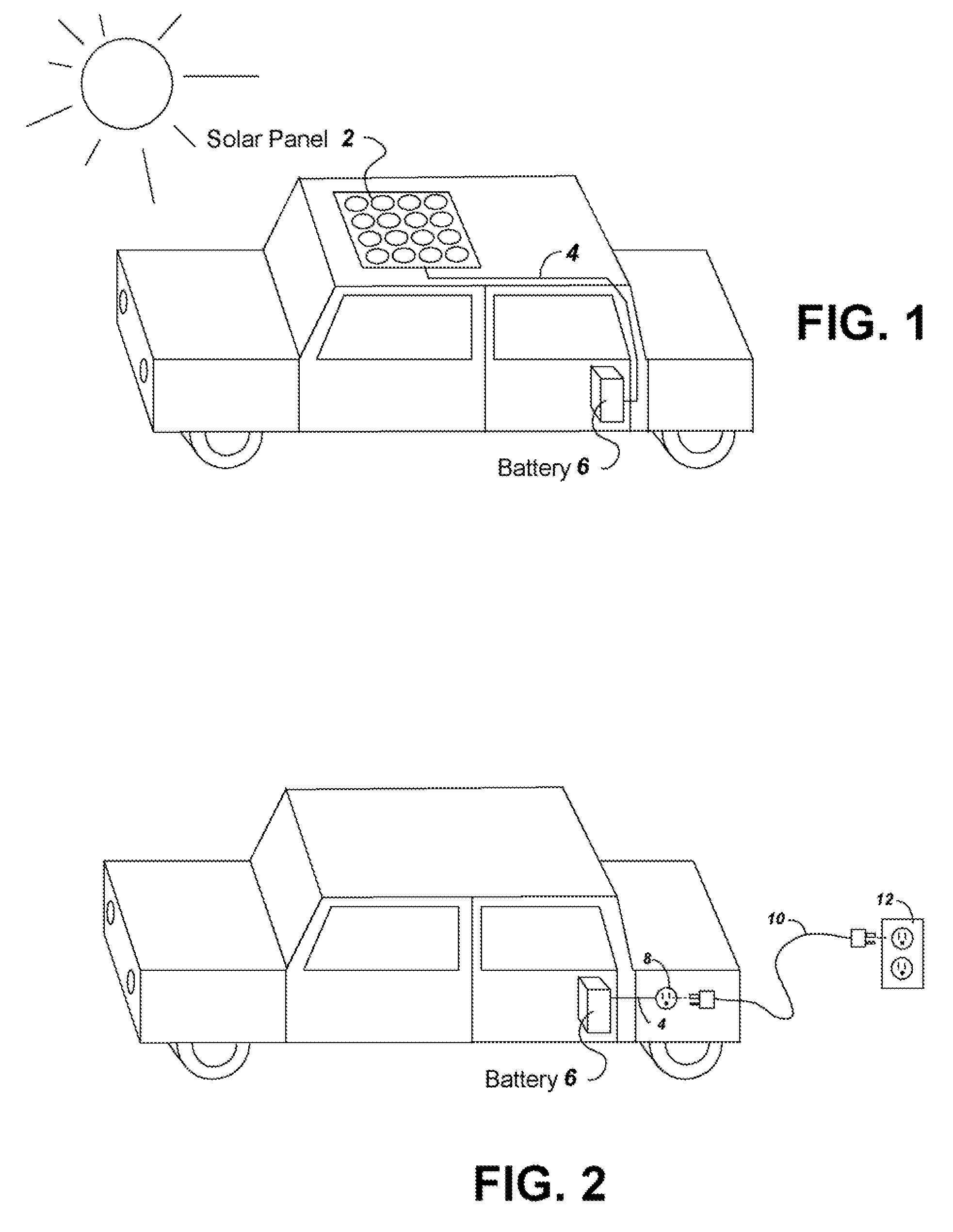
[0025]Embodiments of the present invention allow use of an additional parallel battery that can be charged by a low current charger while preventing overheating. Overheating of the additional battery can otherwise result due to charging by regenerative braking, or discharging when running an electric motor. The low voltage charger can, for example, be a solar panel as illustrated in FIG. 1, or a plug-in charging system as illustrated in FIG. 2.

[0026]FIG. 1 shows a vehicle illustrating a solar panel battery charging system with a solar panel 2 placed on the roof to charge a battery 6 powering an electric motor of the vehicle. Although shown on the roof, it is understood that the solar panel 2 can be attached to a vehicle in a number of ways. Other non-limiting exemplary places to attach a solar panel 2 to a vehicle include providing the solar panel in a moon roof, attaching the solar panel to a roof rack, attaching the solar panel to the trunk or hood of the ca...


PUM


Abstract

To provide additional charge storage for an electric vehicle, an additional battery (100) is connected in parallel with a regenerative braking direct charged battery (22) through a current limiting or clamping circuit (104 or 120). The additional battery (100) is charged by an external charger such as a plug-in charger or a solar panel that supply minimal current to prevent generation of battery heat. Current flows from the additional battery (100) to the regenerative braking charged batteries (22) so that both batteries can be charged. However, when excessive charge is drawn to drive the vehicle electric motor (20), the current limiting or clamping circuit (104 or 120) serves to prevent the discharge of additional battery (100) from creating excessive heat in the additional battery (100). Further, when regenerative braking is applied the current clamping circuit (120), or a diode buffer (102) in combination with current limiter (104), serves to prevent charging from creating excessive heat in the additional battery (100) and eliminates the need for a cooling structure in the additional battery (100).

Description

CLAIM FOR PRIORITY[0001]The present application is a Divisional of U.S. patent application Ser. No. 11 / 887,509 filed Oct. 23, 2007 and which claimed priority to U.S. Provisional Patent Application Ser. No. 60 / 956,647 filed Aug. 17, 2007 and U.S. Provisional Patent Application Ser. No. 60 / 891,356 filed Feb. 23, 2007, all of which are incorporated herein by reference in their entirety.BACKGROUND[0002]1. Technical Field[0003]The present invention relates to a system for increasing the battery power available for an electric vehicle. More particularly, the present invention relates to a system for increasing available battery power when charging is available from a means that supplements regenerative braking.[0004]2. Related Art[0005]Electric vehicles or hybrid vehicles that are powered by a combination of electric and fueled motors include batteries that are typically charged by regenerative braking. Other sources of electric charge power can be provided to the electric powered vehicle...

Claims


Application Information

Patent Timeline
Patent Type & Authority Applications(United States)
IPC IPC(8): H02J7/00
CPCB60L8/003B60L11/1809B60L11/1864H02J7/027Y02T10/7061Y02T10/7005Y02T10/7083Y02T90/14H02J7/35Y02T10/7072B60L53/00B60L58/21H02J2310/48Y02T10/70H02J7/02H02J7/00302H02J7/00309H02J7/0048H02J7/00304
Inventor WARD, THOMAS ALLAN
Owner WARD THOMAS ALLAN
Why Eureka
Try Eureka