Moth-eye film

A moth-eye film and flat film technology, applied in the field of moth-eye film, can solve problems such as generation of dirt, and achieve the effects of preventing condensation and excellent reflectivity.

Active Publication Date: 2015-04-29
SHARP KK
View PDF11 Cites 2 Cited by
  • Summary
  • Abstract
  • Description
  • Claims
  • Application Information

AI Technical Summary

Problems solved by technology

[0004] However, the moth-eye film transmits light by virtually canceling the change in the refractive index of the air interface, so it needs to be attached to the outermost surface of the article. For example, when the moth-eye film is attached to the surface of the window gl

Method used


Image

  • Moth-eye film
  • Moth-eye film
  • Moth-eye film

Examples


Embodiment approach 1

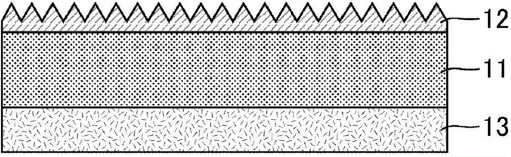
[0076] figure 1 is a schematic cross-sectional view of a laminate including the moth-eye film of Embodiment 1. like figure 1 As shown, the moth-eye film 12 of Embodiment 1 is attached to an article to be an antireflection object through the base film 11 and the adhesive layer 13 . The moth-eye film 12 includes concavo-convex portions and a base portion, and most of the light incident on the surface of the moth-eye film 12 is transmitted between the moth-eye film 12 and the article, so it is possible to obtain a film) far superior anti-reflection effect.

[0077] As an object to be anti-reflection, it can be suitably used for items placed in a low-temperature environment such as window glass of buildings, information displays, display windows, car windshields, rear windows, instrument panels, window glass, etc., but can also be used for Displays, water tanks, printed matter, photographs, painted items, lighting equipment, etc. for mobile phones, etc.

[0078] The material...


PUM

PropertyMeasurementUnit
Widthaaaaaaaaaa
Thicknessaaaaaaaaaa

Abstract

Provided is a moth-eye film wherein dew condensation is not easily generated on the surface thereof. This moth-eye film is formed of a resin composition having a contact angle larger than 5° but smaller than 31.3° when a flat film is formed of the resin composition, a droplet of water is applied to the surface of the flat film, and contact angle is measured with respect to the water after 100 milliseconds.

Description

technical field [0001] The present invention relates to moth eye films. More specifically, it relates to a moth-eye film capable of reducing surface reflection of a substrate by being attached to the substrate. Background technique [0002] In recent years, a moth-eye (Moth-eye: moth's eye) structure, which can obtain a super anti-reflection effect without using an existing light interference film, has attracted attention as a technique for reducing surface reflection of a display device. The moth-eye structure is an anti-reflection treated article on the surface of the anti-glare (AG: Anti Glare) film formed by the concave-convex pattern finer than the concave-convex pattern at intervals below the wavelength of visible light. The change of the refractive index at the boundary between the outside world (air) and the surface of the article is made to be virtually continuous, almost all light is transmitted regardless of the refractive index interface, and light reflection on...

Claims


Application Information

Patent Timeline
IPC IPC(8): G02B1/118G02B27/00E06B7/12
CPCG02B27/0006E06B7/12G02B1/04G02B1/118
Inventor 箕浦洁石动彰信寺西知子佐藤英次
Owner SHARP KK
Why Eureka
Try Eureka