Low voltage reset circuit

A reset circuit, low-voltage technology, applied in electrical components, electronic switches, pulse technology, etc., can solve the problems of increased power consumption and area of ​​circuits, erroneous release of reset signals of high-level pulses, and rapid curve drop, etc., to improve the circuit. performance effect

Active Publication Date: 2018-05-22
西安中颖电子有限公司
View PDF3 Cites 0 Cited by
  • Summary
  • Abstract
  • Description
  • Claims
  • Application Information

AI Technical Summary

Problems solved by technology

Since the bandgap reference source circuit takes a long time to set up, when the system is quickly powered on, the sampling voltage VSAMP drawn from between the first resistor R1 and the second resistor R2 rises faster than the reference voltage VREF, resulting in the sampling voltage The voltage of VSAMP is always greater than the voltage of the reference voltage VREF, and the LVR circuit cannot generate a high-level pulse reset signal, such as Figure 1B shown
Most systems need to add other circuit modules to make up for the problem of fast power-on, but the newly added circuit not only needs to increase power consumption and area, but also has more or less other defects
[0005] 2. Figure 1C for Figure 1A A schematic diagram of the failure of a low-voltage reset circuit in the prior art when the system power is turned off
When the system power supply VDD continues to drop to a certain low voltage, the bandgap reference source circuit cannot work normally under low voltage, causing the curve of the reference voltage VREF to drop rapidly, and a second "intersection" occurs with the curve of the sampling voltage VSAMP, resulting in a high-level pulse Error release of the reset signal, such as Figure 1C shown

Method used


Image

  • Low voltage reset circuit
  • Low voltage reset circuit
  • Low voltage reset circuit

Examples


Embodiment Construction

[0043] The circuit architecture and circuit working principle of the present invention will be further described below in conjunction with specific embodiments and accompanying drawings. In the following description, more details are set forth in order to fully understand the present invention. Those skilled in the art can make similar promotion and deduction according to the actual application situation without violating the connotation of the present invention. Therefore, the content of this specific embodiment should not limit the protection scope of the present invention.

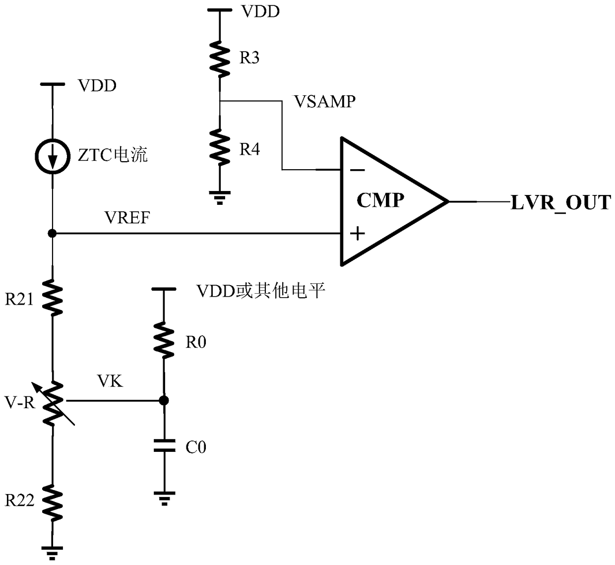
[0044] Figure 2A It is a schematic structural diagram of a low-voltage reset circuit based on a current-mode bandgap reference source main circuit according to an embodiment of the present invention; Figure 2BIt is a schematic structural diagram of a low-voltage reset circuit based on a voltage-type bandgap reference source main circuit according to an embodiment of the present invention. Figure 3A ...


PUM


Abstract

The present invention provides a low-voltage reset circuit, including: a current source, a first resistor, a second resistor, a third resistor, a fourth resistor, a comparator and a voltage-controlled resistor; a current source, a first resistor, a voltage-controlled resistor and a second The resistors are connected in series in sequence, connected between the power supply voltage and the ground; the third resistor and the fourth resistor are connected in series with each other, connected between the power supply voltage and the ground; the negative input terminal of the comparator is drawn between the third resistor and the fourth resistor The sampling voltage is connected; the positive input terminal of the comparator is connected to the reference voltage extracted between the current source and the first resistor; the current source generates a current with zero temperature coefficient or a current with positive temperature coefficient through the main circuit of the bandgap reference source , which in turn is used to generate a stable reference voltage. The present invention can correctly generate a high-level pulse reset signal in the process of fast power-on of the system; in addition, when the system power supply is powered down to ultra-low voltage, the reset signal will not be released by mistake.

Description

technical field [0001] The present invention relates to the technical field of analog integrated circuits or digital-analog hybrid integrated circuits, in particular, the present invention relates to a low-voltage reset circuit. Background technique [0002] The main function of the low-voltage reset (LVR: Low Voltage Reset) circuit is to generate a reset of a high-level pulse (high pulse) of appropriate width when the power supply voltage is lower than the set voltage value during the power-on or power-off process of the system. (reset) signal to reset the system to ensure the stability of all internal digital logic. The LVR circuit is an essential and important circuit module of the microcontroller (MCU) system, and is widely used in the fields of analog integrated circuits and digital-analog hybrid integrated circuits. [0003] Figure 1A It is a schematic structural diagram of a low-voltage reset circuit in the prior art. Traditional high-precision LVR circuits general...

Claims


Application Information

Patent Timeline
Patent Type & Authority Patents(China)
IPC IPC(8): H03K17/22
Inventor 吉博
Owner 西安中颖电子有限公司
Why Eureka
Try Eureka