
Method for manufacturing electrical storage device and electrical storage device

A technology of an electrical storage device and a manufacturing method, which is applied in the manufacture of hybrid/electric double-layer capacitors, lithium storage batteries, and final product manufacturing, etc., can solve the problems of shortened life and reduced reliability of electrical storage devices.

Active Publication Date: 2018-03-23
MUSASHI ENERGY SOLUTIONS CO LTD
View PDF5 Cites 0 Cited by
  • Summary
  • Abstract
  • Description
  • Claims
  • Application Information

AI Technical Summary

Problems solved by technology

As a result, the life of the power storage device may be shortened and the reliability may be lowered.

Method used


Image

  • Method for manufacturing electrical storage device and electrical storage device
  • Method for manufacturing electrical storage device and electrical storage device
  • Method for manufacturing electrical storage device and electrical storage device

Examples


no. 1 approach

[0056] 1.1. Electric storage equipment

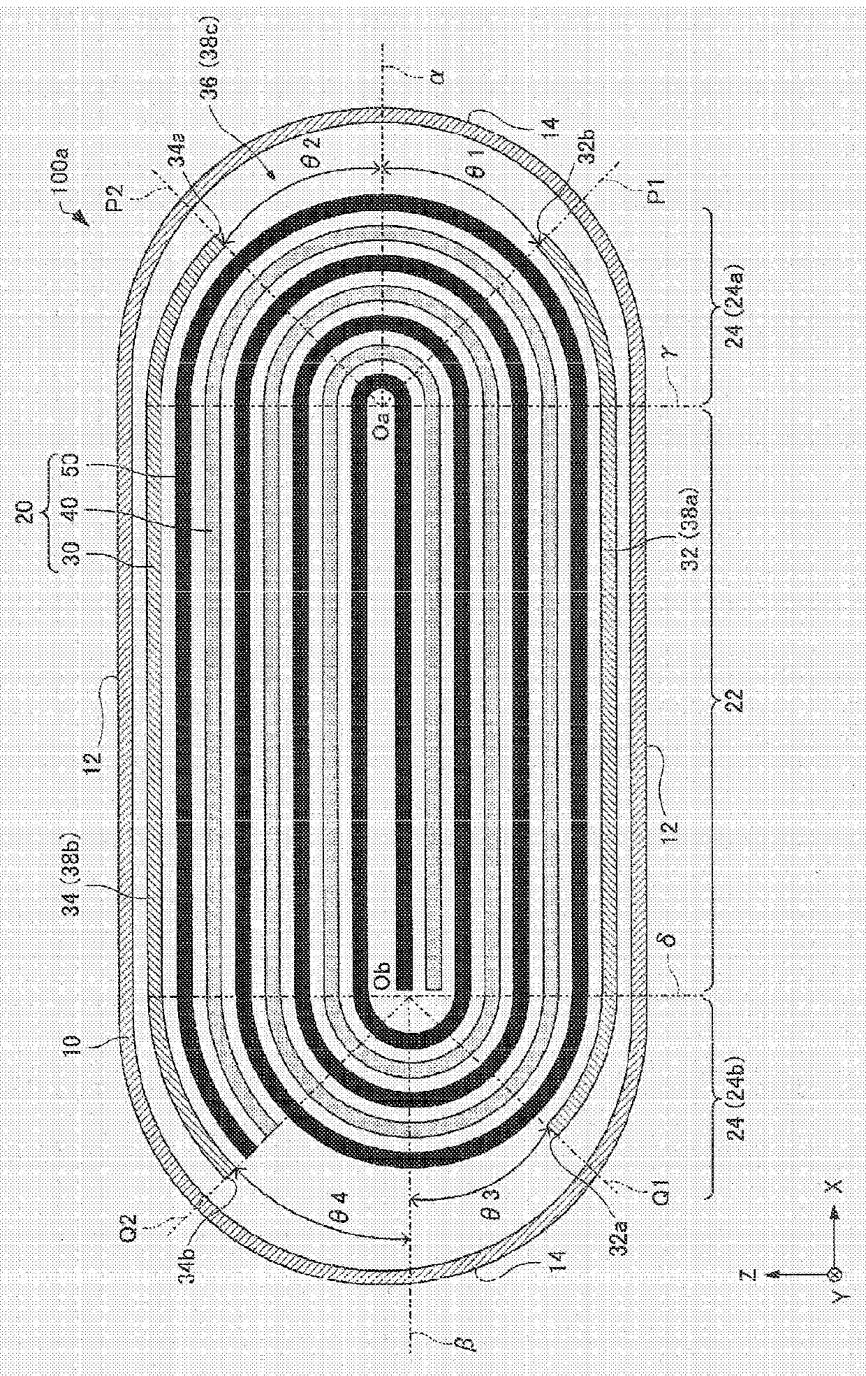
[0057] First, an electrical storage device according to a first embodiment will be described with reference to the drawings. The power storage device according to the first embodiment is formed by doping (hereinafter also referred to as “pre-doping”) the negative electrode 50 with lithium ions released from a lithium ion supply source. More specifically, the electrical storage device according to the first embodiment is formed by accommodating a wound body in an exterior body and injecting an electrolytic solution into the exterior body to perform pre-doping. Hereinafter, first, a state (hereinafter, also referred to as a "cell") before predoping (electrolytic solution injection) will be described, and then an electrical storage device will be described.

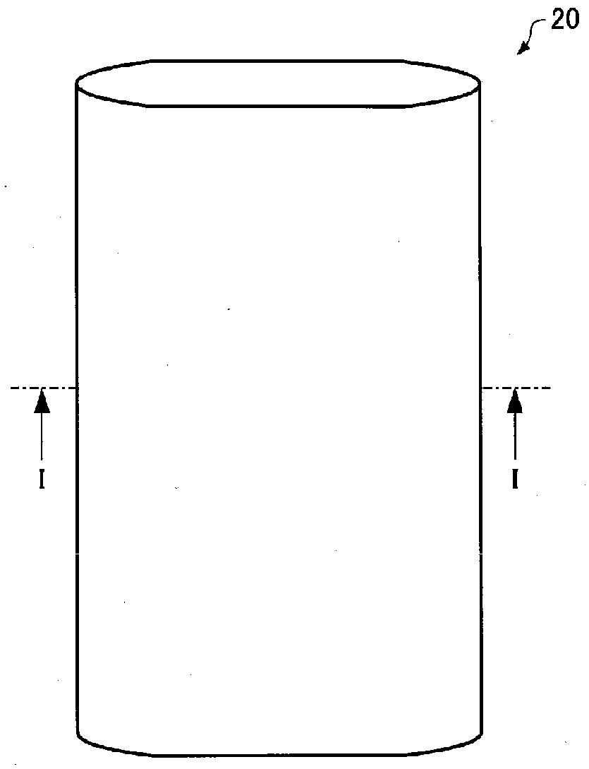
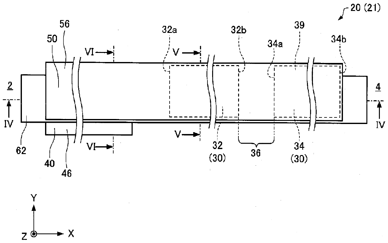
[0058] figure 1 It is a cross-sectional view schematically showing the unit 100a of the first embodiment. figure 2 It is a perspective view which schematically shows the winding b...

no. 2 approach

[0150] 2.1. Electric storage equipment

[0151] Next, an electrical storage device according to a second embodiment will be described with reference to the drawings. The electrical storage device of the second embodiment is formed by doping the negative electrode 50 with lithium ions released from the lithium ion supply source 30 in the same manner as the electrical storage device 100 in the cell of the second embodiment.

[0152] Figure 12 is a cross-sectional view schematically showing a unit 400a of the second embodiment, and figure 1 correspond. Hereinafter, in the unit 400a of the second embodiment, members having the same functions as those of the constituent members of the unit 100a of the first embodiment are denoted by the same reference numerals, and detailed description thereof will be omitted.

[0153] Also, for convenience, in Figure 12 In the figure, the illustration of the first spacer 60 and the second spacer 62 is omitted. In addition, in Figure 12 In...


PUM


Abstract

The method for manufacturing an electrical storage device (100) of the present invention includes a step of forming a wound body (20) wound with a positive electrode (40), a negative electrode (50), and a Lithium ion supply source (30) of a plurality of parts (32), (34) arranged with slits (36), and having a flat part (22) and a curved part (24), in the process of forming a wound body (20) , the wound body (20) is formed in such a way that the slit (36) is located at the curved portion (24).

Description

technical field [0001] The present invention relates to a method of manufacturing an electrical storage device and the electrical storage device. Background technique [0002] In recent years, lithium ion capacitors, which combine the storage principles of lithium ion secondary batteries and electric double layer capacitors, have attracted attention as electrical storage devices for applications requiring high energy density and high output characteristics. Lithium-ion capacitors store and support (hereinafter also referred to as “doping”) lithium ions in the negative electrode in advance by an electrochemical method to lower the potential of the negative electrode, thereby greatly increasing the energy density. [0003] For example, in International Publication No. 2010 / 073930, it is disclosed that in a wound body formed by winding a positive electrode, a negative electrode, and a lithium ion supply source arranged through a separator, by electrochemical contact between the...

Claims


Application Information

Patent Timeline
Patent Type & Authority Patents(China)
IPC IPC(8): H01G11/26H01G11/86H01M10/052H01M10/0587
CPCH01G11/06H01G11/26H01G11/82H01G11/86H01M10/052H01M10/0587Y10T29/42Y10T29/4911Y02E60/10Y02P70/50H01M10/0525H01G11/24Y02E60/13
Inventor 南坂健二千叶隆
Owner MUSASHI ENERGY SOLUTIONS CO LTD
Learn More