Plasma doping apparatus

a technology of plasma doping and apparatus, which is applied in the direction of chemical vapor deposition coating, coating, electric discharge tube, etc., can solve the problems of difficult to reduce the resistance of the diffusion layer formed by plasma doping sheets, and achieve the effect of reducing the doping of the substrate, improving the xj-rs characteristics, and reducing the concentration on the surfa

Inactive Publication Date: 2011-12-15
PANASONIC CORP
View PDF2 Cites 65 Cited by
  • Summary
  • Abstract
  • Description
  • Claims
  • Application Information

AI Technical Summary

Benefits of technology

[0073]In accordance with the present invention, by making the pressure inside the suction groove lower than the pressure inside the vacuum container, the gas inside the vacuum container is sucked into the suction groove, so that a gas flow is formed from the inside of the vacuum container toward the inside of the suction groove between the upper end surface of the vacuum container and the contact surface of the top plate to the vacuum container being opposed to each other. By using this gas flow, air proceeding from the outside of the vacuum container into the vacuum container can be blocked, so that the air is sucked into the suction groove. Alternatively, there is formed a gas passage through which a gas is allowed to flow in a space formed by dividing the space of the vacuum container by an inner chamber, so that air proceeding from the outside of the vacuum container into the vacuum container is directed toward an evacuation side by the gas flow and the air is prevented from proceeding toward the substrate.
[0074]Therefore, by preventing the air leaking into the vacuum container from invading toward the substrate in the vacuum container, it is possible to suppress doping of the substrate with oxygen derived from the leaking air. As a result, the oxide film on the surface of the substrate can be made thinner and the As concentration on the surface is made higher, thereby making it possible to obtain the superior effect of improvement of the Xj-Rs characteristics. It is therefore possible to provide a plasma doping apparatus capable of producing a semiconductor device with a large on-state current.

Problems solved by technology

In the conventional plasma processing apparatuses disclosed in Patent Documents 1, 2 mentioned above and the like, however, an issue arises in which it is difficult to reduce a sheet resistance of a diffusion layer formed by plasma doping.

Method used


Image

  • Plasma doping apparatus
  • Plasma doping apparatus
  • Plasma doping apparatus

Examples


first embodiment

[0105]Referring to FIGS. 1A to 5, the following description will refer to a first embodiment of the present invention.

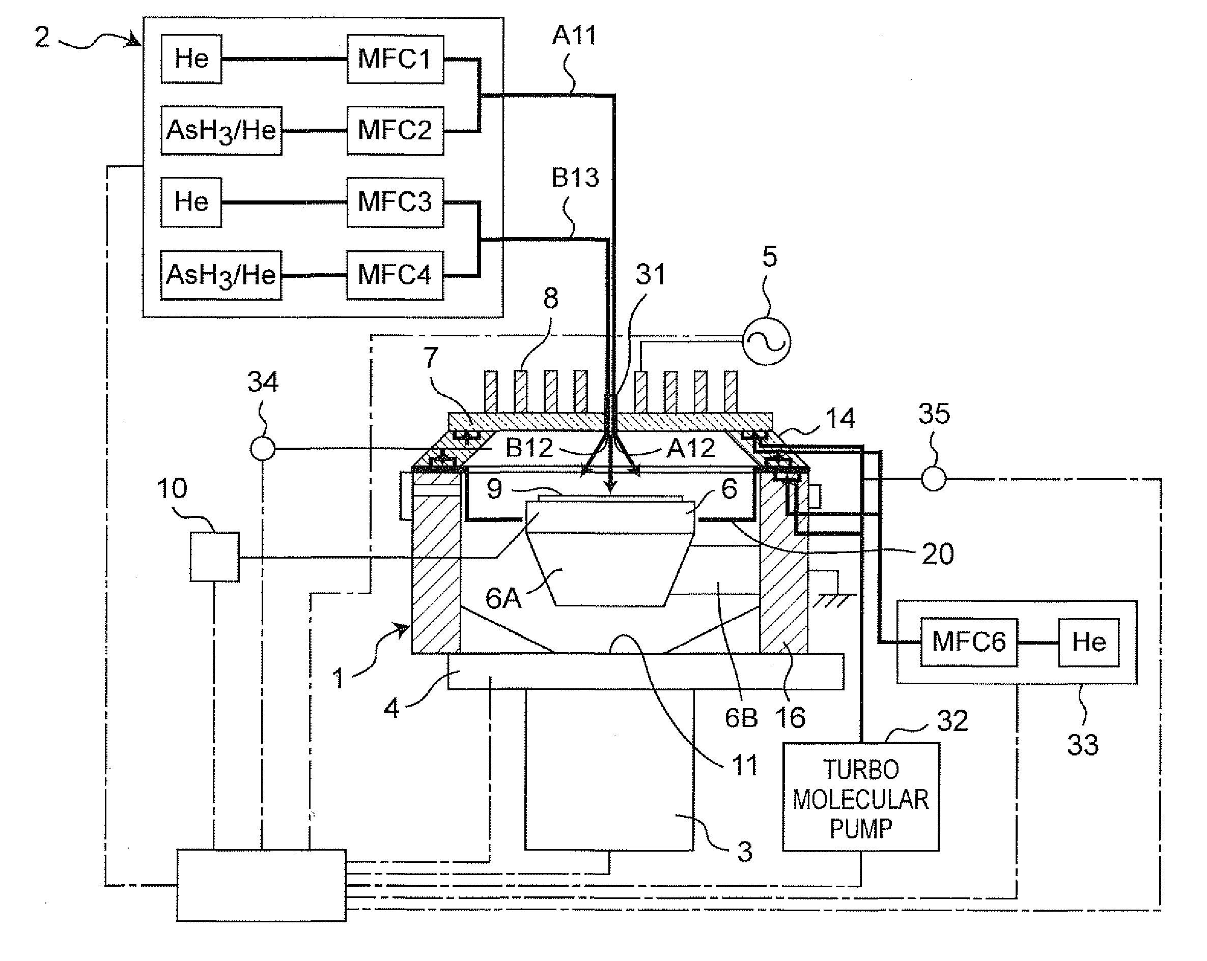
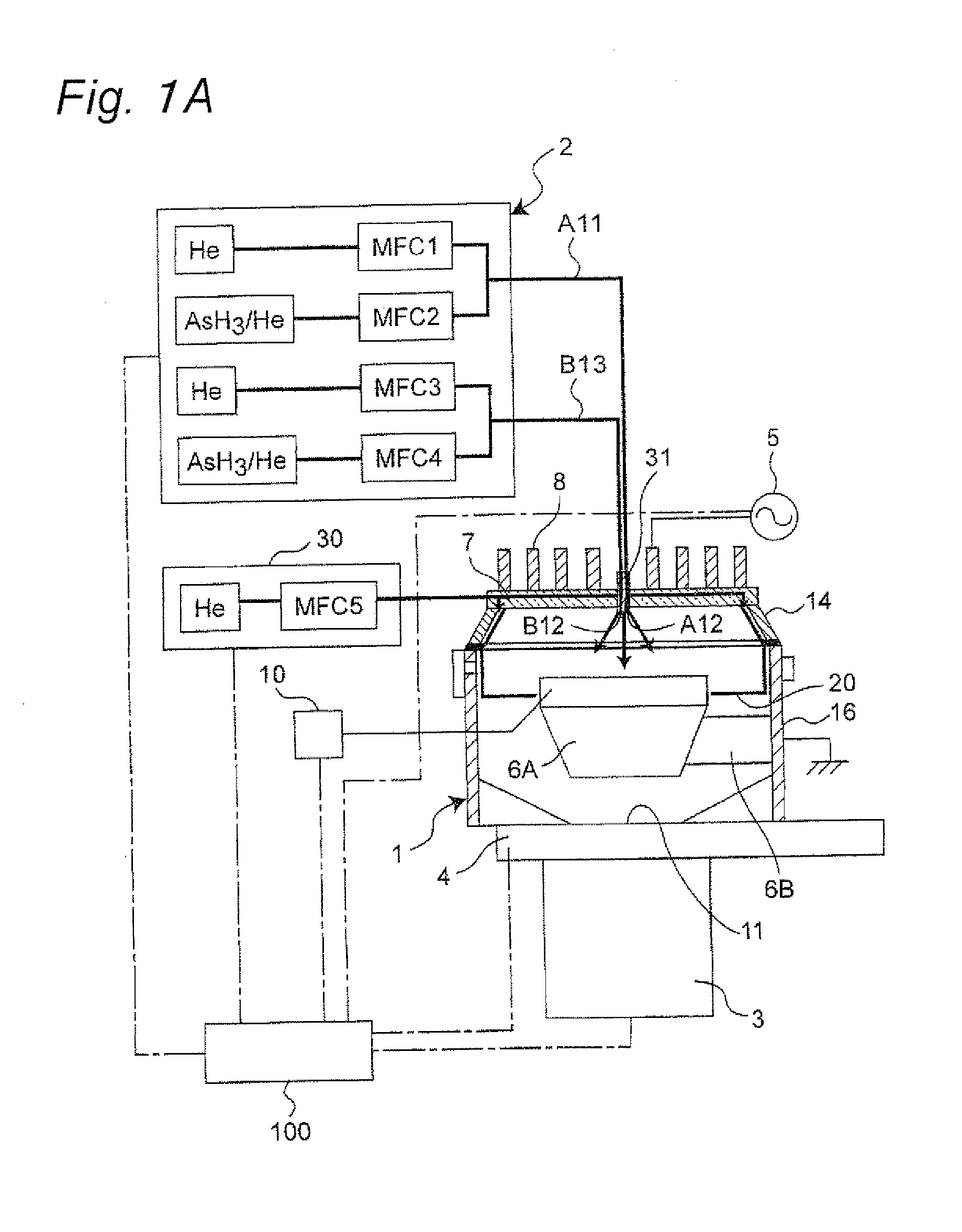
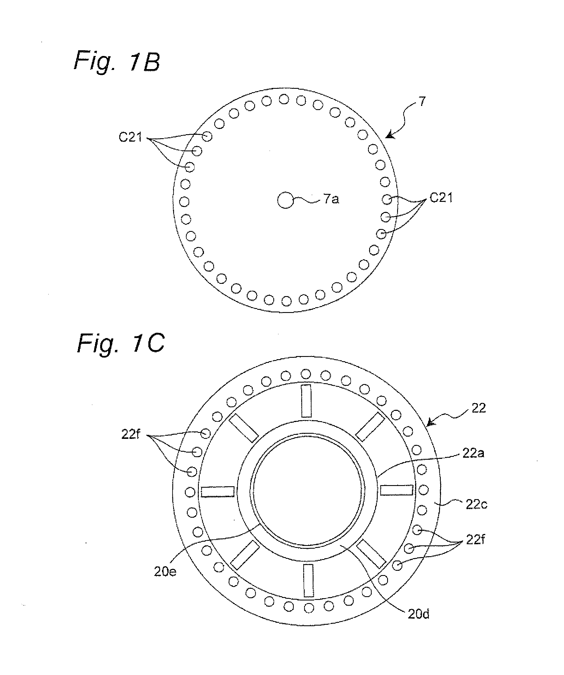
[0106]FIG. 1A is a partial cross-sectional view showing a plasma doping apparatus for use in the first embodiment of the present invention. FIG. 1B is a bottom view showing a top plate 7 of the plasma doping apparatus, and FIG. 1C is a plan view showing an inner chamber 20 of the plasma doping apparatus.

[0107]In FIGS. 1A to 1C, while a predetermined gas is being introduced from a gas supply device 2 into a vacuum container 1 that is provided with the top plate 7 on an upper opening in an upper end surface and is grounded, evacuation is performed by a turbo molecular pump 3 serving as an example of a gas evacuation device, and the inside of the vacuum container 1 can be maintained at a predetermined pressure by a pressure adjusting valve 4. A high-frequency power supply 5 for a coil is used for supplying, with high frequency power of 13.56 MHz, a coil 8 that serves as...

second embodiment

[0140]Referring to FIGS. 6 to 8, the following description will refer to a second embodiment of the present invention.

[0141]FIG. 6 is a partial cross-sectional view showing a plasma doping apparatus for use in the second embodiment of the present invention. The bottom view of a top plate 7 of the plasma doping apparatus of the second embodiment is the same as FIG. 1B of the first embodiment, and the plan view of an inner chamber 20 is also the same as FIG. 1C of the first embodiment.

[0142]In FIGS. 6, 1B, and 1C, while a predetermined gas is being introduced from a gas supply device 2 into a vacuum container 1 that is provided with the top plate 7 on an upper opening in an upper end surface and is grounded, evacuation is performed by a turbo molecular pump 3 serving as one example of a gas evacuation device, and the inside of the vacuum container 1 can be maintained at a predetermined pressure by a pressure adjusting valve 4. A high-frequency power supply 5 for a coil supplies a coil...


PUM

PropertyMeasurementUnit
depthaaaaaaaaaa
depthaaaaaaaaaa
gate lengthaaaaaaaaaa

Abstract

There is provided a regulating gas suction device, which forms a regulating gas flow for use in preventing air outside a vacuum container trying to invade into the vacuum container through a sealing member that tightly closes a gap between an upper end surface of the vacuum container and a peripheral edge of a top pate being opposed to each other from flowing toward a substrate at a coupling portion between the top plate and the vacuum container.

Description

TECHNICAL FIELD[0001]The present invention relates to a plasma doping apparatus for use in introducing an impurity into a surface of a solid-state sample such as a semiconductor substrate.BACKGROUND ART[0002]As a technique for introducing an impurity into a surface of a solid-state sample, a plasma doping method has been known in which an impurity is ionized and the ionized impurity is introduced into a solid-state material at low energy (for example, see Patent Document 1).[0003]FIG. 11 illustrates a schematic structure of a plasma processing apparatus for used in the plasma doping method as a conventional impurity introducing method described in Patent Document 1 mentioned above. In FIG. 11, a sample electrode 202 on which a sample 201 made of a silicon substrate is placed is installed in a vacuum container 200. In the vacuum container 200, a gas supply device 203 for use in supplying a doping material gas containing a desired element, such as B2H6, and a pump 204 for reducing the...

Claims


Application Information

Patent Timeline
Patent Type & Authority Applications(United States)
IPC IPC(8): C23C16/50B05C11/00
CPCH01J37/32412H01L21/2236H01J37/32513H01J37/3244
Inventor NISHIJIMA, OSAMUSASAKI, YUICHIROKUBOTA, MASAFUMIOGURA, MOTOTSUGUOKASHITA, KATSUMI
Owner PANASONIC CORP
Why Eureka
Try Eureka