Integrated antenna provided with metal outer casing

A metal shell and antenna technology, which is applied to antenna equipment with additional functions and other directions, can solve the problems of ugly appearance, destroy the integrity of the metal shell, and cannot achieve the effect of metal appearance, and achieve improved aesthetic effects, wear resistance and aesthetics. effect, intensifying effect

Active Publication Date: 2015-09-30
SHANGHAI AMPHENOL AIRWAVE COMM ELECTRONICS CO LTD
View PDF4 Cites 7 Cited by
  • Summary
  • Abstract
  • Description
  • Claims
  • Application Information

AI Technical Summary

Problems solved by technology

The above-mentioned design method destroys the integrity of the metal shell, making the appearance ugly and unable to achieve an integrated metal appearance effect

Method used


Image

  • Integrated antenna provided with metal outer casing
  • Integrated antenna provided with metal outer casing
  • Integrated antenna provided with metal outer casing

Examples


Embodiment 1

[0030] Generally, the metal casing that participates in radiation as part of the antenna in the communication device needs to be divided into multiple antenna parts, and the conduction between the antenna parts needs to be blocked to improve the performance of the antenna.

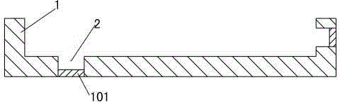
[0031] In this embodiment, the integrated metal shell antenna includes a complete metal shell 1, the material of the metal shell 1 is not limited here, aluminum alloy, magnesium aluminum alloy, stainless steel, carbon steel, alloy steel, iron, Any metal material such as copper or copper alloy; the production process of the metal shell 1 is also not limited, and can be any process such as milling, die-casting, forging, powder metallurgy, etc.

[0032] Such as figure 1 As shown in , on the inner surface of the metal shell 1, thin slots 2 are provided at the divisions of each antenna part, and the parts of the thin slots 2 are non-conductively treated; specifically, the bottom metal part 101 of the thin slot ...

Embodiment 2

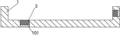
[0035] refer to figure 2 , this embodiment is a conversion embodiment of Embodiment 1. In this embodiment, a non-conductive body 3 may also be provided in the thin groove 2, and a non-conductive body 3 may be partially provided in the thin groove 2, or may be completely filled with non-conductive bodies. The conductor 3 is not limited here; the non-conductor 2 can specifically be made of materials such as plastics, and is arranged in the thin groove 2 through techniques such as nano-molding; the present invention provides reinforcement by setting the non-conductor 3 in the thin groove 2 The metal shell 1, the effect of preventing the corresponding position of the thin groove 2 from breaking.

[0036] For the structure of the remaining parts of the integrated metal case antenna provided in this embodiment, reference may be made to the relevant description in Embodiment 1, and details are not repeated here.

Embodiment 3

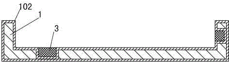
[0038] refer to image 3 , this embodiment is a modified embodiment of Embodiments 1 and 2. In this embodiment, all or part of the surface of the metal casing 1 is treated with non-conductive conduction, thereby forming a non-conductive layer 102 on the surface of the metal casing 1; In the present invention, the non-conductive treatment is carried out on the surface of the metal shell 1 , so as to improve the wear resistance of the metal shell 1 and improve the aesthetic effect of the metal shell 1 .

[0039] refer to Figure 4 , remove part of the non-conductive layer 102 on the inner surface of the metal case, thereby forming the connection point 4, so as to facilitate the conduction between the metal case antenna and other antenna devices.

[0040] For the structure of the rest of the integrated metal case antenna provided in this embodiment, reference may be made to the relevant descriptions in Embodiments 1 and 2, and details will not be repeated here.

[0041] To sum ...


PUM


Abstract

The invention discloses an integrated antenna provided with a metal outer casing. The integrated antenna comprises the metal outer casing, wherein multiple antenna parts are formed on the metal outer casing, fine grooves are formed in separation positions of the antenna parts on the inner surface of the metal outer casing, and the fine grooves are subjected to non-conductivity treatment to cut off electricity conduction among the antenna parts. Specifically, metal parts at bottoms of the fine grooves are subjected to non-conductivity treatment, and the non-conductivity treatment depth is larger than or equal to the thickness of the metal at the bottoms of the fine grooves. The fine grooves are partially or fully filled with non-conductive bodies used for compensating the metal outer casing. The surface of the metal outer casing is subjected to non-conductivity treatment, so that a non-conductive layer is formed, and wear-resistant and attractive effects are realized; connection points are formed after the non-conductive layer on the inner surface of the metal outer casing is partly removed, and oxidation treatment can be used for non-conductivity treatment. The completeness of the metal outer casing is guaranteed, and the attractive effect is good.

Description

technical field [0001] The invention relates to the technical field of antenna design, in particular to an integrated metal shell antenna. Background technique [0002] In the prior art, more and more communication devices use the metal casing as a part of the antenna of the communication equipment to participate in radiation, such as Iphone series mobile phones; the participation of the metal casing in the antenna design is conducive to further utilizing limited space and reducing size. [0003] In order to meet the performance of the antenna and reduce the impact of the metal shell on the performance of the antenna, the metal shell of the conventional mobile terminal product usually needs to be slit on the metal shell, and the metal shell is divided into multiple metal parts to form multiple antenna parts. To block the conduction between the various antenna parts; and the antenna parts formed by each independent metal part are connected by a non-conductive body (such as pl...

Claims


Application Information

Patent Timeline
Patent Type & Authority Applications(China)
IPC IPC(8): H01Q1/44
Inventor 蒋海英蔡士群
Owner SHANGHAI AMPHENOL AIRWAVE COMM ELECTRONICS CO LTD
Why Eureka
Try Eureka