
small lathe
A kind of lathe and small technology, applied in the direction of small lathes, lathes, etc., can solve the problems of complex structure, laborious clamping of parts, low efficiency, etc., and achieve the effect of improving rigidity and stability and reducing the moment of inertia
- Summary
- Abstract
- Description
- Claims
- Application Information
AI Technical Summary
Problems solved by technology
Method used
Image

Examples
Embodiment 1
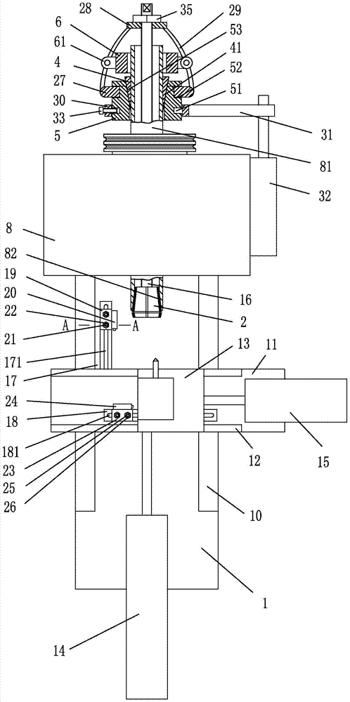
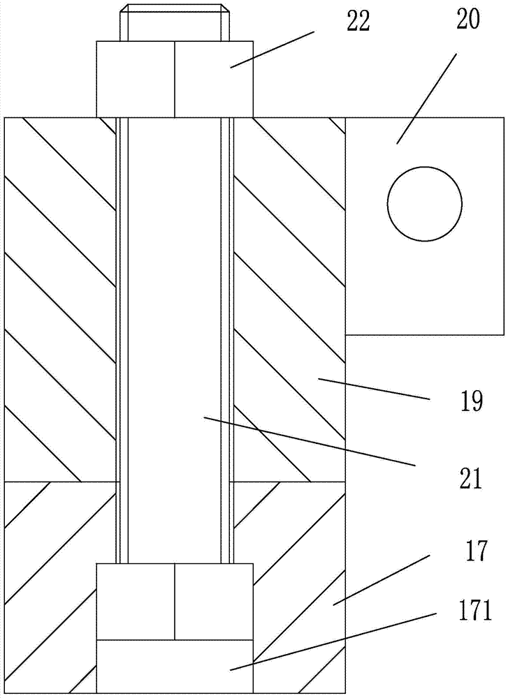
[0017] Embodiment 1, as attached figure 1 , attached image 3 Shown: a small lathe, including a bed 1, a headstock 8 with a spindle 81, a longitudinal carriage 11 connected to the bed 1 through a longitudinal guide rail 10, and a horizontal carriage 11 connected to the longitudinal carriage 11 through a transverse guide rail 12 Plate 13, the longitudinal cylinder 14 whose cylinder rod is screwed to the rear end of the longitudinal carriage 11 and screwed to the bed 1, the horizontal cylinder 15 whose cylinder rod is threaded to the rear end of the horizontal carriage 13 and screwed to the longitudinal carriage 11, The longitudinal limit assembly positioned at the front side of the longitudinal slide 11, the transverse limit assembly positioned at the front side of the horizontal slide 13, the tapered collet 2, the threaded connecting rod 16 and the connecting rod drive assembly; the front end of the main shaft 81 is provided with a cone The tapered hole 82 that the type colle...
Embodiment 2
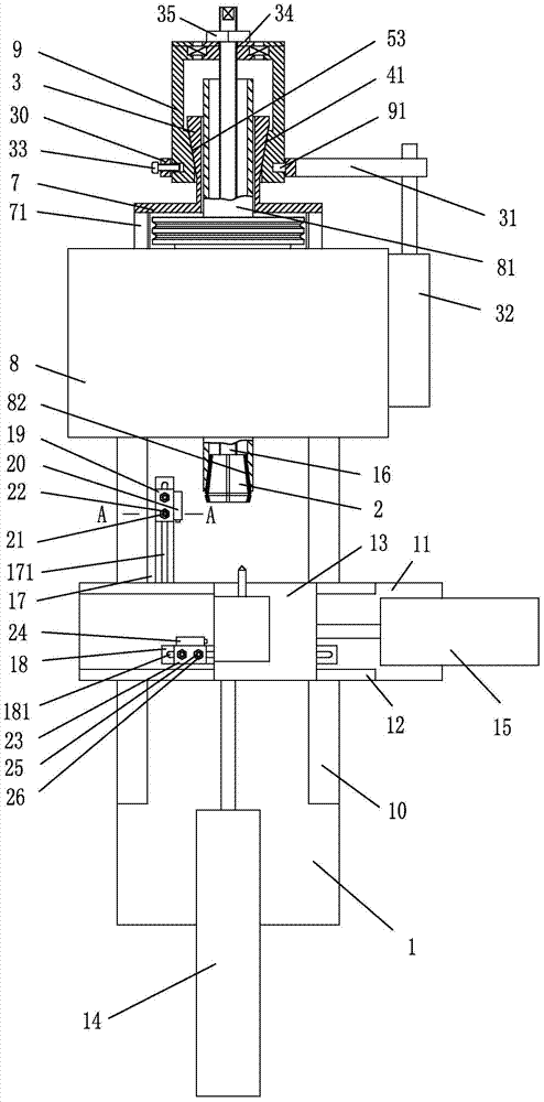
[0023] Embodiment 2, as attached figure 2 , attached image 3Shown: a small lathe, including a bed 1, a headstock 8 with a spindle 81, a longitudinal carriage 11 connected to the bed 1 through a longitudinal guide rail 10, and a horizontal carriage 11 connected to the longitudinal carriage 11 through a transverse guide rail 12 Plate 13, the longitudinal cylinder 14 whose cylinder rod is screwed to the rear end of the longitudinal carriage 11 and screwed to the bed 1, the horizontal cylinder 15 whose cylinder rod is threaded to the rear end of the horizontal carriage 13 and screwed to the longitudinal carriage 11, The longitudinal limit assembly positioned at the front side of the longitudinal slide 11, the transverse limit assembly positioned at the front side of the horizontal slide 13, the tapered collet 2, the threaded connecting rod 16 and the connecting rod drive assembly; the front end of the main shaft 81 is provided with a cone The tapered hole 82 that the type colle...
PUM
 Abstract
Description
Claims
Application Information