
Water-squeezing mop having long service life
A life-saving technology, applied to cleaning carpets, floors, cleaning equipment, etc., can solve the problems of increasing the moving friction of the movable rod, unbalanced force on the cotton head, and reducing the service life, etc., to achieve high water squeezing efficiency , force balance, prolong life effect
- Summary
- Abstract
- Description
- Claims
- Application Information
AI Technical Summary
Problems solved by technology
Method used
Image

Examples
Embodiment Construction
[0022] Below, in conjunction with accompanying drawing and specific embodiment, the present invention is described further:
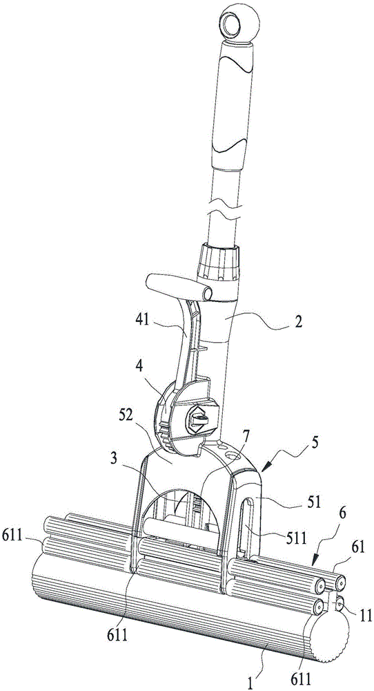
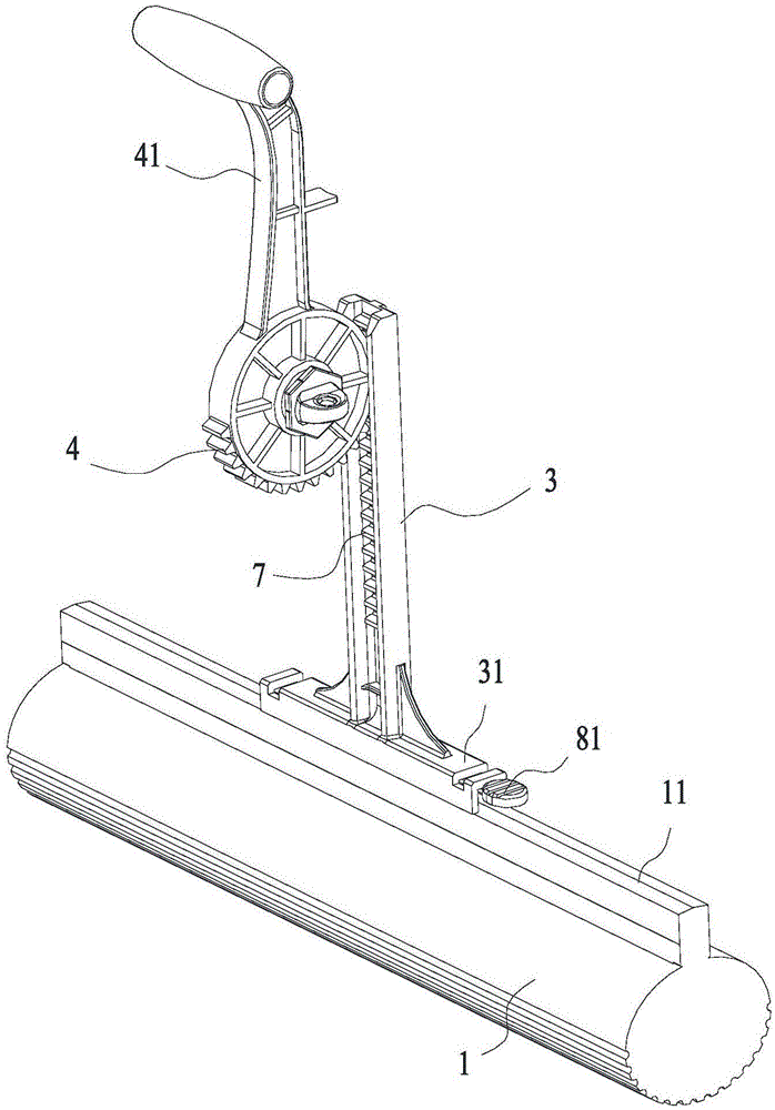
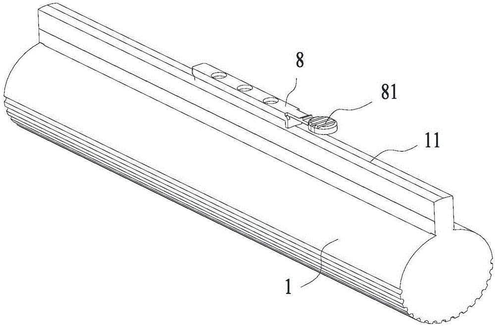
[0023] Such as figure 1 The shown one kind of high-life squeezing floor mop includes a cotton head 1, a tow bar 2, a movable bar 3 and a transmission gear 4, wherein: the tow bar 2 is provided with a fixing frame 5 at the bottom end of the tow bar 2, and the cotton The head 1 is located outside the bottom end of the fixed frame 5, and the two sides of the fixed frame 5 extend outwards with a clamping and squeezing part 6, and the clamping and squeezing part 6 has a clamping and squeezing space for the cotton head 1 to penetrate. The movable rod 3 is movably connected in the tow rod 2 and stretches into the fixed frame 5, and the bottom end of the movable rod 3 is fixedly connected with the cotton head 1, and the shaft of the movable rod 3 is also provided with a The rack 7 extending in the lengthwise direction of 3 is opposite to the clamping water squ...
PUM
 Abstract
Description
Claims
Application Information