Multilayer gear

A gear and gear body technology, applied in belts/chains/gears, components with teeth, portable lifting devices, etc., can solve the problems of difficult processing, long processing time, and high processing costs, and reduce the processing difficulty. The effect of improving mechanical properties and practicability

Inactive Publication Date: 2015-12-09
QUZHOU YOUDE IND DESIGN
View PDF5 Cites 2 Cited by
  • Summary
  • Abstract
  • Description
  • Claims
  • Application Information

AI Technical Summary

Problems solved by technology

[0010] The technical problem solved by the present invention is: in order to solve the technical defects such as complex process, long processing time, high processing difficulty and high processing cost in the prior art, a gear is provided, especially a gear with teeth that is quenched by multiple pieces. A gear made of superimposed thin-sheet parts and filled with molten metal to achieve the technical purpose of low-cost, rapid manufacturing of high-physical performance gears

Method used


Image

  • Multilayer gear
  • Multilayer gear
  • Multilayer gear

Examples


example 1

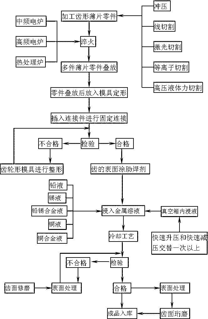
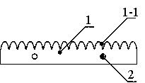
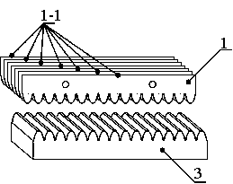
[0074] Example 1: if Figure 1 to Figure 38 As shown, a disclosed multi-layer gear, the gear includes a gear body 5, the gear body 5 is formed by stacking a plurality of quenched toothed sheet parts 1, and at least one of the thin sheet parts 1 is Connecting hole 2, the connecting hole 2 after stacking of multiple sheet parts 1 overlaps to form a through hole, and the connecting holes 2 are fixedly connected with a connecting piece to form a gear body 5, and then the gear body 5 is immersed in the metal solution, and the gear body 5 is formed from the metal solution After being taken out from the medium and cooled, the metal solution is solidified into metal and filled between the thin parts 1 of the gear body 5 and the surface of the gear body 5, and the following processing steps are adopted:

[0075] Step 1): the sheet metal is machined into a toothed sheet part 1; the sheet part 1 has at least one connecting hole 2;

[0076] Step 2): quenching the formed sheet part 1;

...

example 2

[0085] Example 2: if Figure 1 to Figure 4 As shown, the rack is processed by the method of Example 1, and the following processing steps are adopted:

[0086] Step 1): The 45# steel plate with a thickness of 2mm is processed into a sheet rack-shaped part 1-1 by one of the methods of stamping, wire cutting, laser cutting, plasma cutting, and high-pressure liquid force cutting, and a sheet rack-shaped part 1-1 There are two connecting holes 2;

[0087] Step 2): Carry out quenching treatment in the high-frequency coil of electronic high-frequency furnace to the sheet rack-shaped part 1-1 after forming, quenching adopts any one of processes such as high-frequency quenching, intermediate frequency quenching or heat treatment furnace heating and quenching;

[0088] Step 3): Then 15 thin slice rack-shaped parts 1-1 enter the rack-shaped mold for superposition and splicing to form a rack shape, and the connecting holes 2 after the superimposition of 15 thin slice parts 1 overlap to ...

example 3

[0096] Example 3: if Figure 1 to Figure 2 as well as Figure 5 to Figure 7 As shown, the method of Example 1 or 2 is used to process long racks. When producing long racks, the specific arrangement method of thin slice rack-shaped parts 1-1 is: first, on the rack-shaped mold, more than one thin slice tooth The bar-shaped parts 1-1 are connected to form a long rack-shaped sheet part, and then the multi-layer connection to form a long rack-shaped sheet part is superimposed. The multi-layer spliced ​​long rack-shaped thin sheet parts form a long rack shape, and the connecting holes of the stacked long rack-shaped thin sheet parts overlap to form through holes.


PUM


Abstract

The invention relates to a multilayer gear. In order to overcome the technical defects that in the prior art, the gear machining process is complex, the machining time is long, the machining difficulty is large, and the machining cost is high, the gear is provided. The gear comprises a gear body which is formed by laminating a plurality of quenched sheet parts with teeth, at least one connecting hole is formed in each sheet part, the connecting holes are laminated to form a through hole after the sheet parts are laminated, and the connecting holes are fixedly connected into the gear body through connecting pieces; then the gear body is soaked into a metal solution; the gear body is taken out from the metal solution to be cooled; and the metal solution solidifies into metal to be injected into the positions between the sheet parts of the gear body and the surface of the gear body, and the technical aim of rapidly manufacturing the gear with the high physical property in a low-cost manner is achieved.

Description

technical field [0001] The invention relates to a multi-layer gear, in particular to a gear which is superimposed by a plurality of quenched toothed sheet parts and filled with molten metal. Background technique [0002] Gears refer to the mechanical elements with teeth on the rim that can continuously mesh to transmit motion and power. The initial gear transmission in China has been used since the Three Kingdoms period, and there have been records of gear transmission in foreign countries in 300 BC. Therefore, gear transmission in It has been widely used in the field of machinery since ancient times. [0003] Common gears can be divided into gears with circular cross-section, racks and special-shaped gears with non-circular cross-section from the appearance. [0004] Commonly used gear processing methods are generally divided into profiling processing method and fan forming method, such as: hobbing machine gear processing, milling machine gear milling processing, slotting ...

Claims


Application Information

Patent Timeline
Patent Type & Authority Applications(China)
IPC IPC(8): B23P15/14F16H55/17F16H55/12
Inventor 吴超
Owner QUZHOU YOUDE IND DESIGN
Why Eureka
Try Eureka