Brake lamp control system based on CAN network and control method thereof

A technology of control system and brake controller, which is applied in the direction of optical signal, signal device, transportation and packaging, etc. It can solve the problems of rear-end collision accident and driver's lack of time to step on the brake, so as to improve safety, reduce wiring harness connection and expand functions good sex effect

Active Publication Date: 2015-12-09
CHERY AUTOMOBILE CO LTD
View PDF6 Cites 7 Cited by
  • Summary
  • Abstract
  • Description
  • Claims
  • Application Information

AI Technical Summary

Problems solved by technology

Traditionally, the brake light can be turned on only when the driver steps on the brake pedal, but in many cases, such as a brake pedal failure or an emergency, the driver is too late to step on the brake, resulting in the failure to turn on the brake light in time to convey the brake information to the driver. Rear-end accidents caused by vehicles behind

Method used


Image

  • Brake lamp control system based on CAN network and control method thereof
  • Brake lamp control system based on CAN network and control method thereof
  • Brake lamp control system based on CAN network and control method thereof

Examples


Embodiment Construction

[0022] Below with reference to the accompanying drawings, through the description of the implementation examples, the specific embodiments of the present invention, such as the shape, structure, mutual position and connection relationship between each part, the role and working principle of each part, etc., will be further described. detailed instructions.

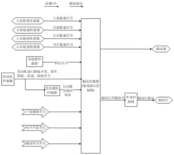
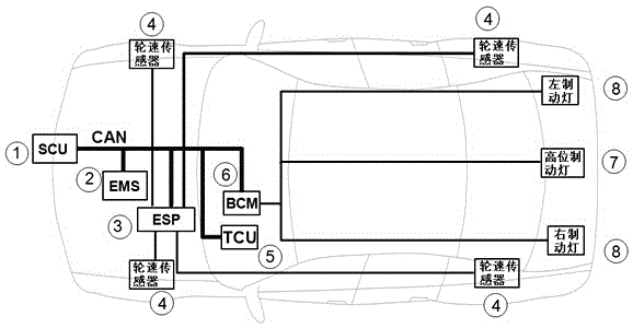
[0023] like figure 1 , the brake light control system based on the CAN network of the present invention, the input end, the brake controller and the output end, the input end includes the wheel speed sensor input, the downhill auxiliary switch input, the electronic handbrake switch input, the brake normally open switch input , gear position signal input, engine controller signal input, and radar ranging controller input for measuring the safe distance in front of the vehicle. The output terminal includes the brake connected to the brake controller, the body controller, the body controller and the brake light Connection, a...


PUM


Abstract

The invention provides a brake lamp control system based on a CAN network and a control method thereof to improve the security of driving. The system comprises an input end, a brake controller, and an output end. The input end comprises wheel speed sensor input, downhill auxiliary switch input, electronic hand brake switch input, brake normally open switch input, gear signal input, engine controller signal input, and radar ranging controller input used to measure the safe distance in front of a vehicle. The output end comprises a brake connected with the brake controller, and a vehicle body controller connected with a brake lamp. The wheel speed sensor input, the downhill auxiliary switch input, the electronic hand brake switch input and the brake normally open switch input are connected with the brake controller by a rigid line. The gear signal input, the engine controller signal input and the radar ranging controller input are connected with the brake controller by a CAN bus. According to the invention, various driving conditions of a vehicle are judged, vehicle braking is executed when there is danger but the driver fails to react, and the vehicle body controller is requested to turn on or off the brake lamp to reduce the occurrence of accidents.

Description

technical field [0001] The invention relates to the technical field of automobile electronic control, in particular to a CAN network-based brake light control system and a control method thereof. Background technique [0002] With the rapid development of the automobile industry, cars have gradually entered thousands of households and become a necessary means of transportation. Casualties and property damage also gradually increased. Automobile safety performance and related devices are getting more and more attention. Brake lights play an important role in transmitting traffic information in car driving. They are one of the important signal devices for cars to warn the rear vehicles to slow down or stop, and to ensure driving safety. Traditionally, the brake light can be turned on only when the driver steps on the brake pedal, but in many cases, such as a brake pedal failure or an emergency, the driver is too late to step on the brake, resulting in the failure to turn on ...

Claims


Application Information

Patent Timeline
Patent Type & Authority Applications(China)
IPC IPC(8): B60Q1/44
Inventor 肖玲
Owner CHERY AUTOMOBILE CO LTD
Why Eureka
Try Eureka