
A drawer that can be locked in any position
A technology for arbitrary positions and drawers, applied to drawers, furniture parts, household appliances, etc., can solve the problems of complex locking device structure, inconvenient operation, unreliable locking, etc., and achieve the effect of simple structure, convenient transmission, and convenient operation
- Summary
- Abstract
- Description
- Claims
- Application Information
AI Technical Summary
Problems solved by technology
Method used
Image

Examples
Embodiment Construction
[0028] The present invention will be described in further detail below in conjunction with the accompanying drawings and embodiments.
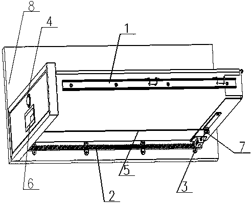
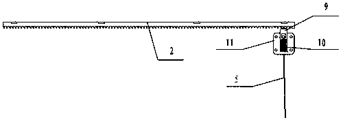
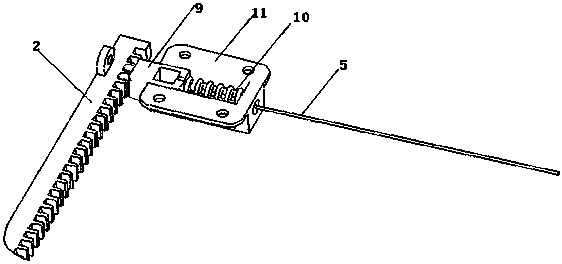
[0029] Such as Figure 1 to Figure 4 As shown, a drawer that can be locked at any position includes a drawer body, a drawer wall 8 and a locking device (the drawer body slides relative to the drawer wall 8 through the slide rail 1), and the locking device includes a latch mechanism 3 , a button mechanism 4, a wire rope 5 and a rack 2 fixed on the drawer wall 8 and arranged along the entire sliding stroke, the bolt mechanism 3 includes a bolt 9, a spring 10 and a guide block fixed on the bottom edge of the drawer body 11. The guide block 11 is provided with an open slot pointing to the rack 2, the lock tongue 9 and the spring 10 are arranged in the open slot and the lock tongue 9 is located on the side close to the rack 2, and the button mechanism 4 includes a The support 14 on the front baffle plate 20 of the main body, the guide sleeve 13 lo...
PUM
 Abstract
Description
Claims
Application Information