

A drawer type switch cabinet
A switch cabinet and drawer type technology, applied in the field of power distribution system equipment, can solve problems such as affecting the accuracy of opening holes, unable to meet customer needs, inconvenient to install electronic devices, etc., to achieve the effect of easy maintenance
- Summary
- Abstract
- Description
- Claims
- Application Information
AI Technical Summary
Problems solved by technology
Method used
Image

Examples
Embodiment Construction
[0021] The present invention will be described in further detail below in conjunction with specific embodiments and accompanying drawings.
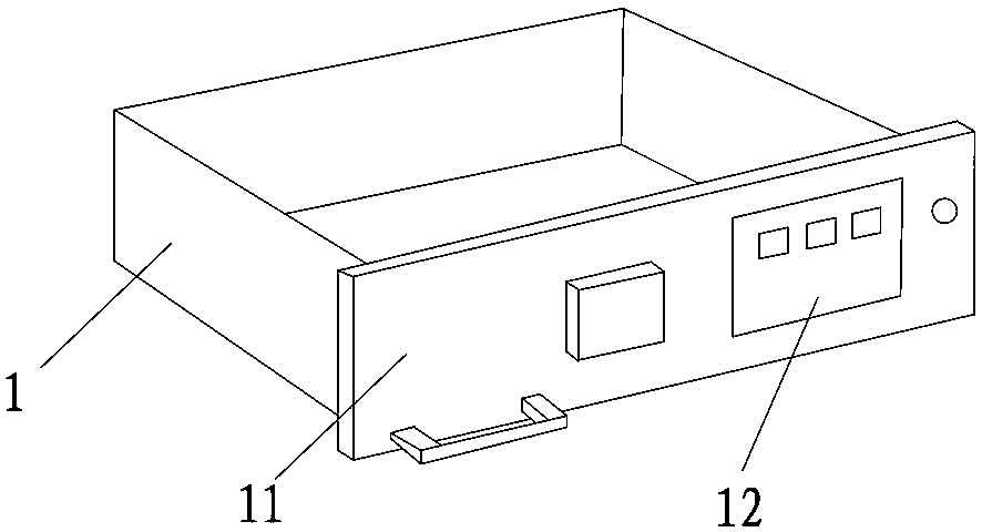
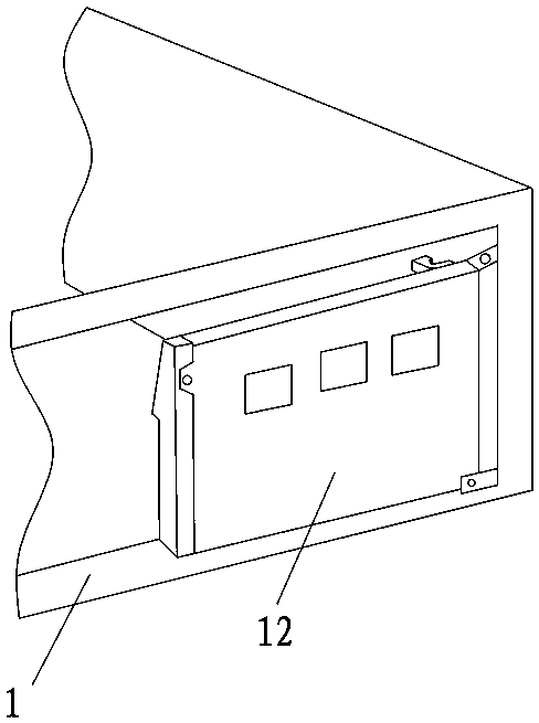
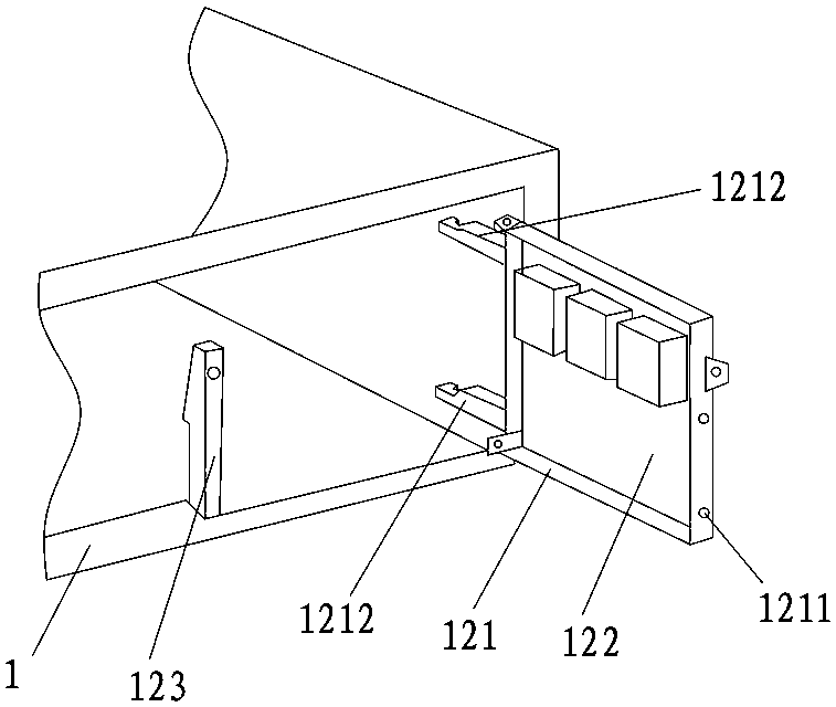
[0022] Such as Figure 1 to Figure 3 As shown, the present invention provides a drawer type switchgear, including a drawer body 1 installed with electronic components, an observation window is provided on the movable front panel 11 of the drawer body 1, and a corresponding observation window is provided on the drawer body 1 for installation. The movable multifunctional plate assembly 12 of the multifunctional meter and the signal lamp is hinged with the drawer body 1 . When the movable front panel 11 of the drawer body 1 is in the closed state, the observation window on the movable front panel 11 just coincides with the movable multifunctional board assembly 12, so that the staff can directly view and read the information installed on the movable multifunctional board through the observation window. The working status and information of ...
PUM
 Abstract
Description
Claims
Application Information