Tool changing and locking structure and automatic machine tool

A locking structure and knife locking technology, applied in metal processing machinery parts, clamping, support and other directions, can solve problems such as the inability of the tool to disengage and the damage to the knife

Active Publication Date: 2016-02-10
SHENZHEN SEEKOO TECH
View PDF6 Cites 4 Cited by
  • Summary
  • Abstract
  • Description
  • Claims
  • Application Information

AI Technical Summary

Problems solved by technology

[0004] The purpose of the present invention is to provide a locking structure for tool change, which aims to solve the problem that the tool cannot be separated from the main shaft during the tool change of the existing machine tools with small diameter tools, resulting in damage to the tool

Method used


Image

  • Tool changing and locking structure and automatic machine tool
  • Tool changing and locking structure and automatic machine tool
  • Tool changing and locking structure and automatic machine tool

Examples


Embodiment Construction

[0011] In order to make the object, technical solution and advantages of the present invention clearer, the present invention will be further described in detail below in conjunction with the accompanying drawings and embodiments. It should be understood that the specific embodiments described here are only used to explain the present invention, not to limit the present invention.

[0012] The implementation of this embodiment will be described in detail below in conjunction with specific drawings.

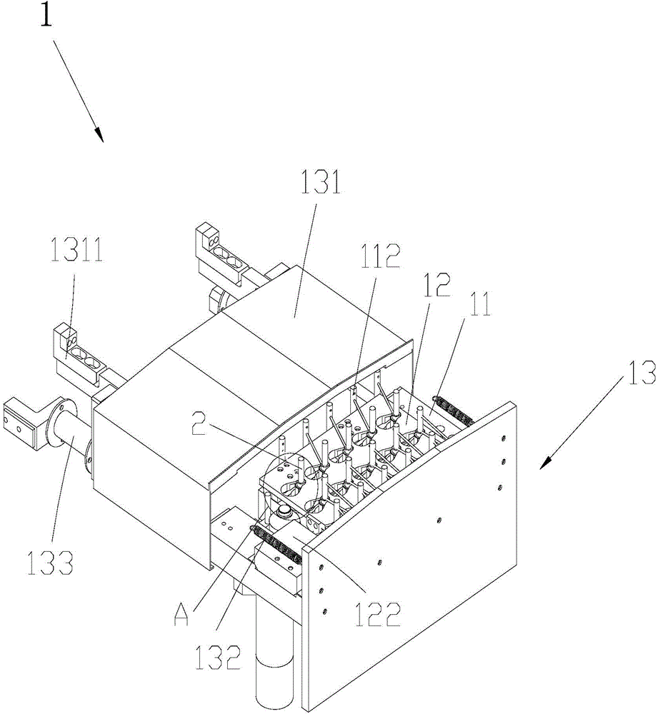
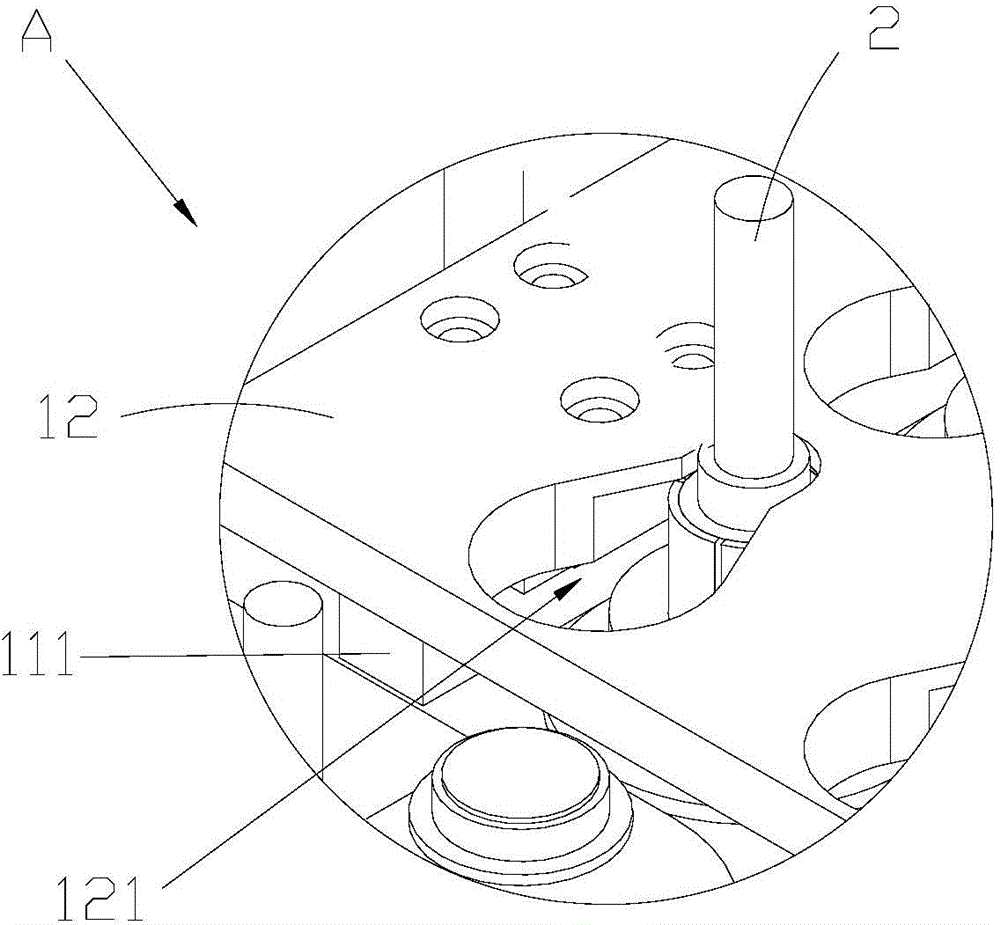
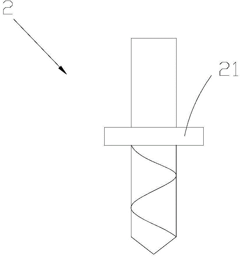
[0013] Such as figure 1 As shown, the tool magazine 1 includes a base 11 on which a plurality of tool positions are arranged, and the tool 2 can be vertically inserted and placed in the tool positions. The tool changing locking structure includes a clamping part arranged in the middle of the tool 2 , a knife locking plate 12 and a knife locking driver, and the knife locking plate 12 is provided with a plurality of locking structures corresponding to each knife position. The lock...


PUM


Abstract

The invention relates to the technical field of machining, and discloses a tool changing and locking structure and an automatic machine tool. The tool changing and locking structure is used for locking tools in a tool storeroom when the tools are released by a main shaft; the tool storeroom comprises a base; the base is provided with multiple tool locations which are used for enabling the tools to vertically insert and place. The tool changing and locking structure comprises clamping parts which are arranged at the middle parts of the tools, a tool locking plate which is arranged above the base and can horizontally slide relative to the base, and a tool locking driving piece which is used for driving the tool locking plate, wherein locking structures which can be used for clamping the clamping parts along with the moving of the tool locking plate are arranged in positions, which correspond to the tool locations, of the tool locking plate. According to the tool changing and locking structure disclosed by the invention, the tool locking plate moves transversely when the main shaft descends to release the tools, and the clamping parts of the tools can be clamped by utilizing the locking structures, so that the tools cannot ascend along with the main shaft, tool releasing can be completed, and the problem that tool collision damage is caused as the main shaft does not fall off cannot happen.

Description

technical field [0001] The invention relates to the technical field of machining, in particular to a tool changing locking structure and an automatic machine tool. Background technique [0002] In modern machining, automatic machine tools can complete automatic tool change, multiple processing, and complete multiple processing steps fully automatically. In the process of tool change, the spindle needs to move and align the tool to the tool position of the tool magazine, descend to insert the tool into the tool position, release the tool, the tool falls into the tool position, and then the spindle rises and moves to align to other tool positions , descending again to insert the required tool holder into the spindle, clamping and rising to complete the tool change process. [0003] Although this tool change method can cope with most machine tool changes, in ultra-precision machining machine tools, because the small tools used, such as φ3, φ5, etc., have a small weight, the ir...

Claims


Application Information

Patent Timeline
Patent Type & Authority Applications(China)
IPC IPC(8): B23Q3/155
Inventor 许晓明
Owner SHENZHEN SEEKOO TECH
Why Eureka
Try Eureka