A lifting and rotating lamp

A technology of lifting and rotating lamps, applied in lighting devices, fixed lighting devices, electric light sources, etc., can solve the problems of inconvenient climbing, high installation position of lamps, and falling from high altitudes, and avoid the inconvenience and convenience of manual control of angles. Imprecise, small size, cleverly designed effects

Active Publication Date: 2018-02-09
OPPLE LIGHTING
View PDF5 Cites 0 Cited by
  • Summary
  • Abstract
  • Description
  • Claims
  • Application Information

AI Technical Summary

Problems solved by technology

Regrettably, traditional lamps cannot meet people's needs at all
People will encounter many difficulties when adjusting the irradiation angle of traditional lamps. For example, the installation position of the lamps is very high, and it is inconvenient for people to climb up. Very high, easy to burn when touched by human hands, etc.

Method used


Image

  • A lifting and rotating lamp
  • A lifting and rotating lamp
  • A lifting and rotating lamp

Examples


Embodiment Construction

[0040] The advantages of the present invention will be further elaborated below in conjunction with specific embodiments and accompanying drawings.

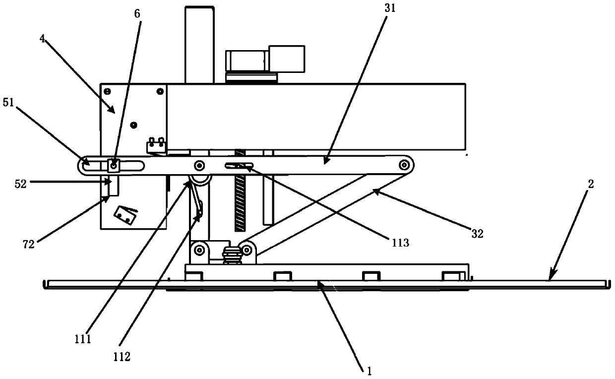
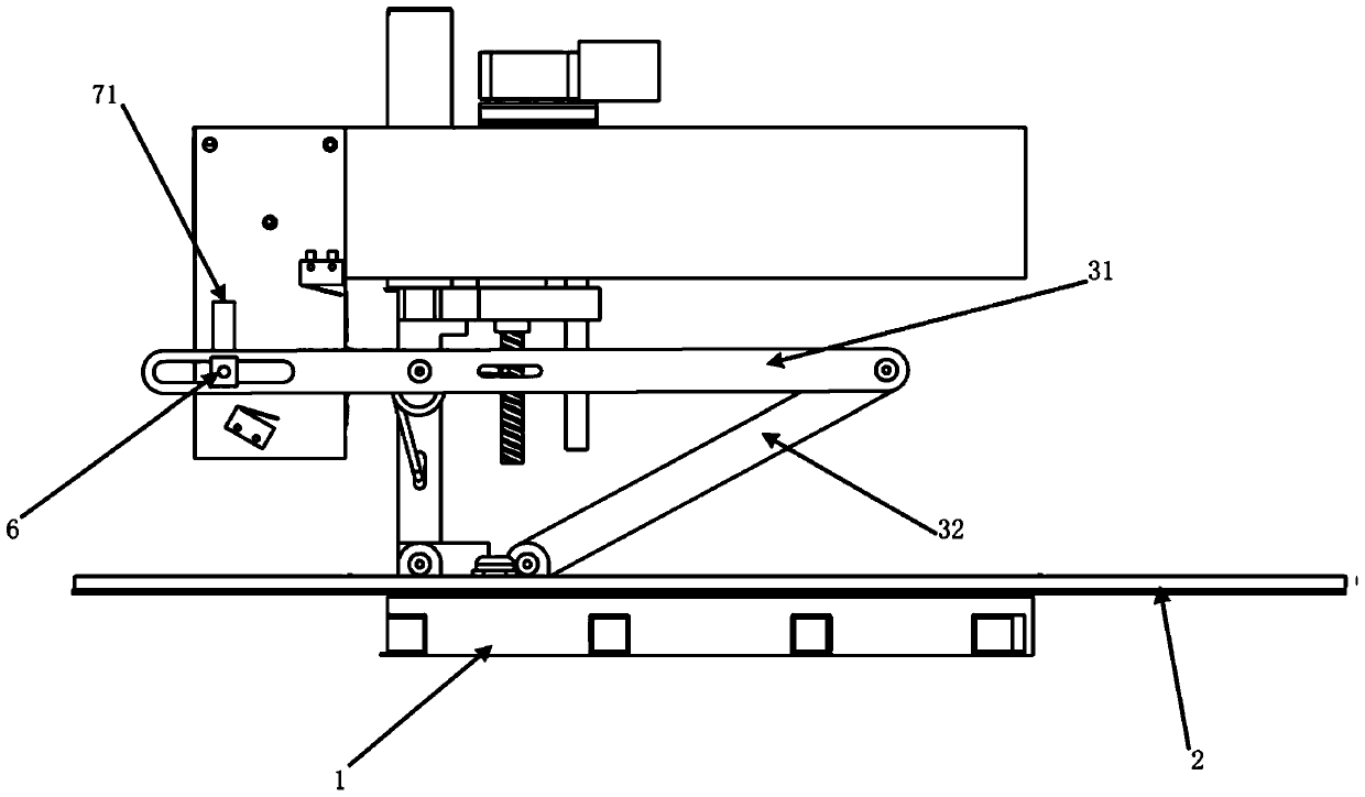
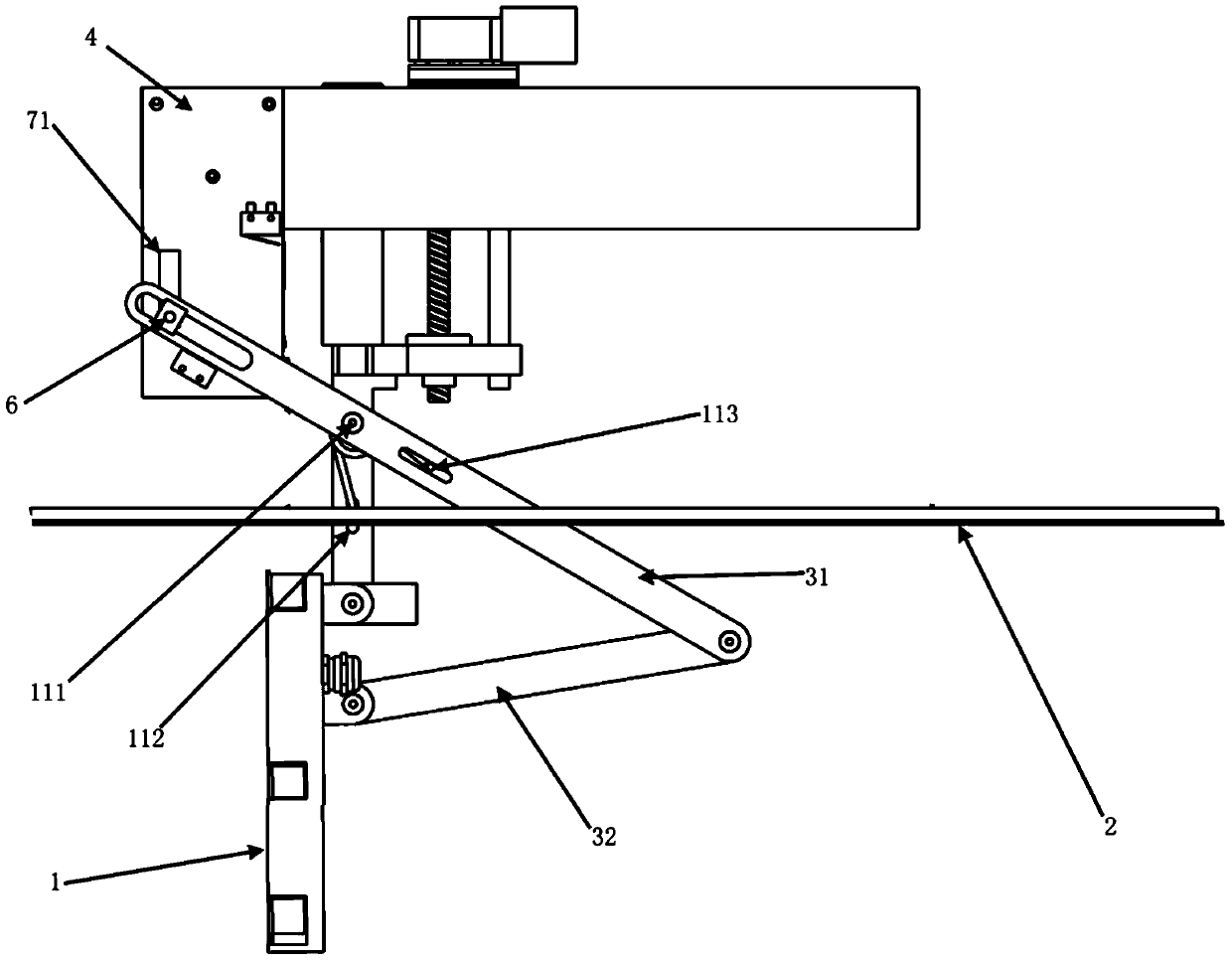
[0041] like figure 1 and figure 2 As shown, the lifting and rotating lamp includes a lamp body 1, a driving device, a lifting device and a rotating device. The entire lifting and rotating lamp is fixed in the ceiling 2. When the lifting and rotating lamp is in the initial state, the lamp body 1 is flush with the ceiling 2, that is, the angle between the lamp body 1 and the ceiling 2 is 0 degree. The driving device is connected with the lifting device and can drive the lifting device to move up and down. The rotating device includes a crank connecting rod and a limiter 4 , and the crank connecting rod includes a first connecting rod 31 and a second connecting rod 32 . One end of the first connecting rod 31 has a first limiting groove 51 extending along the axial direction of the first connecting rod 31 , and the other end of t...


PUM


Abstract

The invention discloses a lifting and rotating lamp which comprises a lamp body, a drive device, a lifting device and a rotating device. The drive device is connected with the lifting device and drives the lifting device to move vertically. The lifting device is further connected with the rotating device. The lamp body is connected with the lifting device and the rotating device at the same time. The lifting device drives the lamp body and the rotating device to move vertically when moving vertically, and when the rotating device moves to a first position or a second position, the rotating device drives the lamp body to rotate so that the lamp body can change the illumination angle. By means of the device, the lamp can ascend and descend, and the illumination angle of the lamp can be freely changed within the scope ranging from 0 to 180 degrees.

Description

technical field [0001] The invention relates to a lamp, in particular to a lifting and rotating lamp. Background technique [0002] Traditional light fixtures are usually fixed directly to the ceiling and can only illuminate from one angle. However, in real life, people often need to adjust the illumination angle of the lamps, such as during a meeting, or in a shopping mall to illuminate items at a specific location. Regrettably, traditional lamps cannot meet people's needs at all. People will encounter many difficulties when adjusting the irradiation angle of traditional lamps. For example, the installation position of the lamp is very high, and it is inconvenient for people to climb up. It is very high, and it is easy to burn when touched by human hands. Contents of the invention [0003] In order to overcome the above-mentioned technical defects, the object of the present invention is to provide a lifting and rotating lamp. [0004] The invention discloses a lifting...

Claims


Application Information

Patent Timeline
Patent Type & Authority Patents(China)
IPC IPC(8): F21S8/04F21V21/15
Inventor 何雄飞顾选雄
Owner OPPLE LIGHTING
Why Eureka
Try Eureka