Disinfection cabinet

A technology of disinfection cabinet and disinfection chamber is applied in the field of disinfection cabinet to achieve the effect of improving disinfection effect and uniformity

Inactive Publication Date: 2020-12-25
NINGBO FOTILE KITCHEN WARE CO LTD
View PDF8 Cites 2 Cited by
  • Summary
  • Abstract
  • Description
  • Claims
  • Application Information

AI Technical Summary

Problems solved by technology

[0004] However, in the above scheme, a circulation channel needs to be set in the interlayer between the shell and the liner, and for ultraviolet disinfection, there is still a disinfection dead angle

Method used


Image

  • Disinfection cabinet
  • Disinfection cabinet
  • Disinfection cabinet

Examples


Embodiment 1

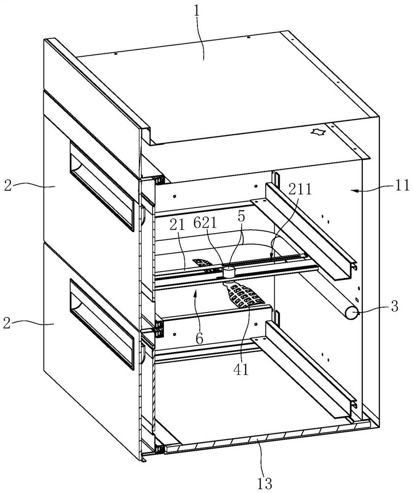
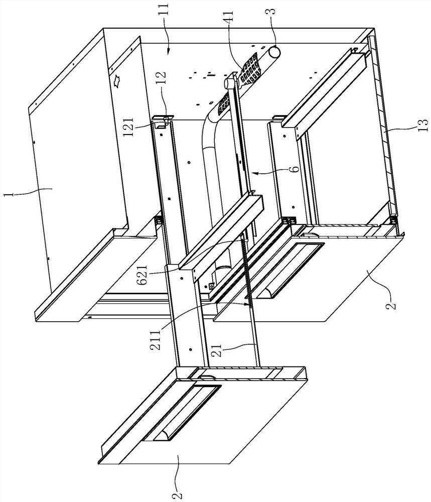
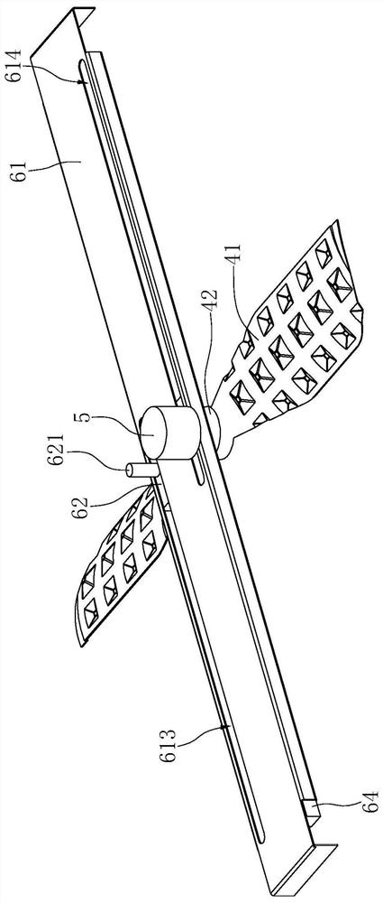
[0047] Such as Figure 1 to Figure 5 Shown is the first preferred embodiment of the disinfection cabinet of the present invention. The disinfection cabinet includes a cabinet body 1 , a drawer 2 , a disinfection lamp tube 3 , a fan 4 , a driving part 5 and a transmission assembly 6 .

[0048] Wherein, the inside of the cabinet 1 has a disinfection chamber 11, a door control switch 12 is installed on the rear side wall of the disinfection chamber 11, and a contact 121 corresponding to the drawer 2 is arranged on the door control switch. A heating element 13 is installed. In this embodiment, the heating element 13 is flat, and serves as a planar heating source to heat the disinfection chamber 11 .

[0049] There are two drawers 2, which can be pulled in and out of the disinfection chamber 11, and are arranged in the disinfection chamber 11 one above the other. The bottom of the drawer 2 located above is equipped with a bar-shaped limit seat 21 extending along the depth direct...

Embodiment 2

[0058] Such as Figure 6 Shown is the second preferred embodiment of the disinfection cabinet of the present invention. The difference with Example 1 is:

[0059] In this embodiment, the fan blade 41' of the fan 4' has a wavy cross-section, so that several concave and convex surfaces are formed on the surface facing the disinfection lamp 3, wherein the concave surface can gather light The converging light can increase the local light intensity and achieve a better disinfection effect in a shorter time; the convex surface can diverge the light, and the divergent light helps to improve the uniformity of the light in the disinfection chamber 11 and reduce the dead angle of the light.

[0060] Taking Embodiment 1 as an example, the working principle of the present invention is as follows:

[0061] (1) When disinfecting, if figure 1 As shown, the drawer 2 is in the closed state, the fan 4 and the driving part 5 are located in the middle of the disinfection chamber 11, the drawer...


PUM


Abstract

The invention discloses a disinfection cabinet which comprises a cabinet body (1) internally provided with a disinfection cavity (11), drawers (2) capable of being drawn in and out of the disinfectioncavity (11), a heating piece (13) capable of heating the disinfection cavity (11), and a disinfection lamp tube (3) mounted in the disinfection cavity (11), and is characterized by further comprisinga fan (4, 4') and a driving part (5), wherein the fan (4, 4') is located in the disinfection cavity (11) and comprises fan blades (41, 41') and a rotating shaft (42) connected to the ends of the fanblades (41, 41'), the surfaces of the fan blades (41, 41') are made of a material capable of reflecting disinfection light rays, and a power output shaft of the driving part (5) is in transmission connection with the rotating shaft (42) to enable the fan blades (41, 41') to rotate around the axis of the rotating shaft (42). Compared with the prior art, the disinfection cabinet has the advantage that the disinfection effect and uniformity can be improved.

Description

technical field [0001] The invention relates to the technical field of kitchen equipment, in particular to a disinfection cabinet. Background technique [0002] At present, disinfection cabinets mainly use ultraviolet disinfection, heating disinfection and ozone disinfection. In order to improve the disinfection effect, a combination of two disinfection factors or three disinfection factors is usually used, or the intensity of ultraviolet rays and the concentration of ozone are increased by changing the position, quantity, shape and parameters of the disinfection lamps, or the disinfection time is extended. Or circulate the air in the disinfection chamber. [0003] Such as patent application number is CN03228333.4 (announcement number is CN2596987Y) utility model patent "a kind of disinfection cabinet with circulating air duct" discloses a kind of disinfection cabinet with circulating air duct, including housing, liner, and In the cavity between the two, there is a circula...

Claims


Application Information

Patent Timeline
Patent Type & Authority Applications(China)
IPC IPC(8): A61L2/10A61L2/06A61L2/20A61L2/26A61L101/10
CPCA61L2/06A61L2/10A61L2/202A61L2/26
Inventor 张文龙
Owner NINGBO FOTILE KITCHEN WARE CO LTD
Why Eureka
Try Eureka