Measuring method of humidity-controllable semiconductor gas sensitive element

A technology of gas sensing element and testing method, applied in humidity control, heating method, measuring device, etc., can solve the problems of long desorption time of sample gas, unsuitable for gas testing, etc.

Inactive Publication Date: 2016-03-09
DALIAN NATIONALITIES UNIVERSITY
View PDF4 Cites 11 Cited by
  • Summary
  • Abstract
  • Description
  • Claims
  • Application Information

AI Technical Summary

Problems solved by technology

Usually, the static test system adopts a closed large-capacity gas chamber, which injects sample gas and mixes it uniformly in the container to form a certain volume of test gas...

Method used


Image

  • Measuring method of humidity-controllable semiconductor gas sensitive element
  • Measuring method of humidity-controllable semiconductor gas sensitive element
  • Measuring method of humidity-controllable semiconductor gas sensitive element

Examples


Embodiment 1

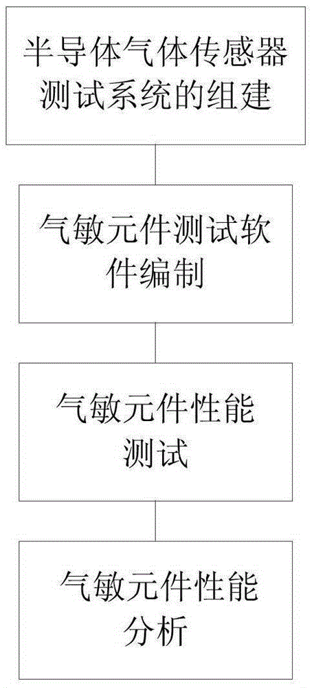
[0067] A test method for a humidity-controllable semiconductor gas sensor, comprising: SnO 2 The steps of preparing gas-sensitive materials, the steps of making gas-sensitive elements, the steps of building and testing the semiconductor gas sensor test system, and the steps of analyzing the performance of the semiconductor gas sensor test system and the semiconductor gas-sensitive element.

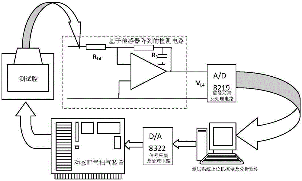
[0068] The step of setting up and testing the gas sensor testing system has a step of controlling the humidity of the air chamber. In this step, a humidity control system is used, including a main controller, a humidity detection sensor, a dehumidifier, an ultrasonic humidifier and The buzzer, wherein the humidity detection sensor, the dehumidifier and the ultrasonic humidifier are installed in the air chamber, and the main controller is respectively connected with the humidity detection sensor, the dehumidifier, the ultrasonic humidifier and the buzzer.

Embodiment 2

[0070] Have the same technical scheme as embodiment 1, more specifically: SnO 2 The steps of gas-sensitive material preparation are: with SnCl 4 ·5H 2 O as raw material, dilute ammonia water as precipitant, weigh a certain amount of SnCl 4 ·5H 2 O raw material, dissolved in an appropriate amount of deionized water, added a small amount of citric acid, stirred to make it completely dissolved, then heated to boiling, and made to react; the prepared dilute ammonia water was slowly added dropwise to the SnCl 4 When the precipitation is complete, wash with warm water and centrifuge for several times to remove the Cl-, then dry the precipitate at 60-100°C, grind it and put it in the muffle furnace Burn at about 700°C for 2 to 4 hours to obtain SnO 2 gas sensitive material.

Embodiment 3

[0072] It has the same technical solution as that of Embodiment 1 or 2, more specifically: in the step of making the gas sensor, the tube core of the sensitive element has a capillary ceramic tube, and the heating wire penetrates into the ceramic tube, The outer coated metal electrode is used as the signal electrode for measuring the resistance of the element, and the gas sensitive material SnO is coated on the outer metal electrode. 2 , and fired;

[0073]The production steps are as follows: the substrate of the ceramic tube coated with metal electrodes at both ends is ultrasonically cleaned with toluene, alcohol and deionized water in sequence, and after drying under the infrared lamp, the ground slurry is coated on the surface of the ceramic tube. and then sintered in a tube-type resistance furnace. Finally, a heating wire with a suitable resistance value is inserted into the burned tube core, and the electrode lead and the heating wire lead are welded on the tube seat of t...


PUM


Abstract

The invention discloses a measuring method of a humidity-controllable semiconductor gas sensitive element, belonging to the field of element measurement and solving the problem that the existing measuring method of a formaldehyde gas sensitive element is incomplete and is low in humidity control precision. The technical point is as follows: the measuring method comprises the steps of building and measuring a semiconductor gas sensor measuring system, in which a humidity control system is used and comprises a main controller, a humidity detection sensor, a dehumidifier, an ultrasonic humidifier and a buzzer, wherein the humidity detection sensor, the dehumidifier and the ultrasonic humidifier are mounted in a gas chamber, the main controller is respectively connected with the humidity detection sensor, the dehumidifier, the ultrasonic humidifier and the buzzer. Through use of the measuring method, the measurement of the formaldehyde gas sensitive element is more complete, and the controllability and control precision of the humidity are improved.

Description

technical field [0001] The invention belongs to the field of element testing, in particular to a method for testing a humidity-controllable semiconductor gas sensor. Background technique [0002] When the development of semiconductor gas sensor technology is in full swing, the development of semiconductor gas sensor testing technology has not kept pace with the development of gas sensor technology. Human beings' understanding and transformation of the objective world are often based on testing work. Engineering testing technology is a new technology that uses modern testing methods to detect, test, and analyze various signals in engineering, especially dynamic physical signals that change with time, and extract useful information from them. The results of its measurement and analysis objectively describe the state, changes and characteristics of the research object, and provide a reliable basis for further transformation and control of the research object. Similarly, the r...

Claims


Application Information

Patent Timeline
IPC IPC(8): G01N27/00
CPCF24F3/14G01N27/00G01N27/12G01N27/125G05D22/02
Inventor 杜海英孙炎辉李正王述刚
Owner DALIAN NATIONALITIES UNIVERSITY
Why Eureka
Try Eureka