Optical eyepiece lens and head-mounted display device

A technology of eyepiece and lens, which is applied in the field of optical eyepiece lens and head-mounted display equipment, can solve the problems of affecting the user's eye health, short exit pupil distance of the lens, unfavorable use, etc., and achieve light and thin structure design, good turning light, The effect of meeting consumer demand

Inactive Publication Date: 2016-03-09
郑茹文
View PDF7 Cites 21 Cited by
  • Summary
  • Abstract
  • Description
  • Claims
  • Application Information

AI Technical Summary

Problems solved by technology

[0005] Chinese Patent Publication Nos. CN104635333A, CN104536129A, and CN101887166A disclose three optical eyepiece lenses composed of three lenses respectively, but there are still problems such as short exit pupil distance, short working distance, and low magnification of the lens. Among them, China Patent Publication No. CN101887166A The length of the exit pupil distance of the lens is within 11mm,

Method used


Image

  • Optical eyepiece lens and head-mounted display device
  • Optical eyepiece lens and head-mounted display device
  • Optical eyepiece lens and head-mounted display device

Examples


no. 1 example

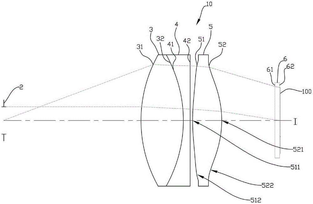
[0071] refer to figure 1 and image 3 , The first embodiment of the optical eyepiece lens 10 of the present invention includes a diaphragm 2, a first lens 3, a second lens 4, a third lens 5 and a protective glass 6 in sequence along the optical axis I from the observation side to the image source side. When the light emitted by the display screen 100 enters the optical eyepiece lens 10, passes through the protective glass 6, the third lens 5, the second lens 4, the first lens 3 and the diaphragm 2, enters the human eye, and forms an upright magnified image. It should be added that the object side is the side facing the image source, and the image side is the side facing the observer.

[0072] Wherein, the first lens 3, the second lens 4, the third lens 5 and the cover glass 6 all have image side surfaces 31, 41, 51, 61 facing the image side and allowing the imaging light to pass through, and facing the object side and allowing the imaging light to pass through. Passing obje...

no. 2 example

[0087] refer to Figure 5, is the second embodiment of the optical eyepiece lens 10 of the present invention, which is roughly similar to the first embodiment, wherein the main difference between this second embodiment and the first embodiment is that the second lens 4 The object side surface 42 of the third lens 5 is a convex surface (42), and the object side surface 52 of the third lens 5 has a concave portion 522 located in the vicinity of the circumference. It should be noted here that in order to clearly show the figure, Figure 5 In , the reference numerals of the concave portion and the convex portion that are the same as those of the first embodiment are omitted.

[0088] Its detailed optical data such as Figure 7 As shown, the overall system focal length of the second embodiment is 12.69 mm, the half angle of view (HFOV) is 20.5°, the exit pupil diameter is 3 mm, and the system length is 41.49 mm. Such as Figure 8 As shown, are the various aspheric coefficients i...

no. 3 example

[0092] refer to Figure 9 , is the third embodiment of the optical eyepiece lens 10 of the present invention, which is roughly similar to the first embodiment, only the optical data, aspheric coefficients and parameters between the lenses 3, 4, and 5 are more or less different, It should be noted that, in order to clearly show the figure, Figure 9 In , the reference numerals of the concave portion and the convex portion that are the same as those of the first embodiment are omitted.

[0093] Its detailed optical data such as Figure 11 As shown, the overall system focal length of the third embodiment is 12.22 mm, the half angle of view (HFOV) is 20.5°, the exit pupil diameter is 3 mm, and the system length is 41.51 mm. Such as Figure 12 As shown, are the various aspheric coefficients in the formula (1) from the image side 51 to the object side 52 of the third lens 5 of the third embodiment.

[0094] In addition, the relationship between each important parameter in the op...


PUM

PropertyMeasurementUnit
Total lengthaaaaaaaaaa
Focal lengthaaaaaaaaaa
Angle of viewaaaaaaaaaa

Abstract

The invention discloses an optical eyepiece lens and a head-mounted display device. The optical eyepiece lens sequentially comprises, from a human eye observation side to an image source side and along an optical axis, a diaphragm, a first lens, a second lens, and a third lens. The first lens, the second lens and the third lens all have a refractive index, and each comprise an image plane which faces the observation side and allows imaging light to pass through and an object plane which faces the image source side and allows imaging light to pass through. The first lens and the third lens are positive lenses, and the second lens is a negative lens. The first lens is a biconvex lens, the second lens is a plane-concave lens, a biconcave lens or a meniscus lens, and the third lens is an aspheric lens. The invention provides an optical eyepiece lens and a head-mounted display device which still have good optical performance under the condition that the length of the lens system is shortened.

Description

technical field [0001] The invention relates to an optical eyepiece lens, in particular to an optical eyepiece lens for a micro-display head-mounted display device and the head-mounted display device. Background technique [0002] Head-mounted display devices are widely welcomed by consumers due to their small size and light weight. In particular, the large field of view of the device can create an immersive and shocking visual effect for the user, making the user feel like watching a movie in a movie theater projection hall. [0003] The image source device of the head-mounted display device in the prior art widely adopts a whole large-sized OLED (Organic Light-Emitting Diode) and LCD (Liquid Crystal Display) screen, and the lens used with it has a short working distance, a short exit pupil distance, and a long focal length. , low magnification and other characteristics, but the average screen resolution is slightly insufficient for a single eye. Another type of display d...

Claims


Application Information

Patent Timeline
IPC IPC(8): G02B25/00G02B27/01G02B7/02
CPCG02B25/001G02B27/0172G02B2027/011
Inventor 叶龙江虹
Owner 郑茹文
Why Eureka
Try Eureka