Illumination device and display device

A technology for lighting devices and display areas, which is applied to lighting devices, lighting device parts, lighting and heating equipment, etc., can solve problems such as the reduction of brightness of convex parts, and achieve the effect of suppressing uneven brightness and uniform lighting

Inactive Publication Date: 2016-05-11
SAKAI DISPLAY PROD
View PDF4 Cites 1 Cited by
  • Summary
  • Abstract
  • Description
  • Claims
  • Application Information

AI Technical Summary

Problems solved by technology

[0009] As for the convex part that engages with the concave part of the light guide plate, since t

Method used


Image

  • Illumination device and display device
  • Illumination device and display device
  • Illumination device and display device

Examples


Example Embodiment

[0064] Embodiment 1

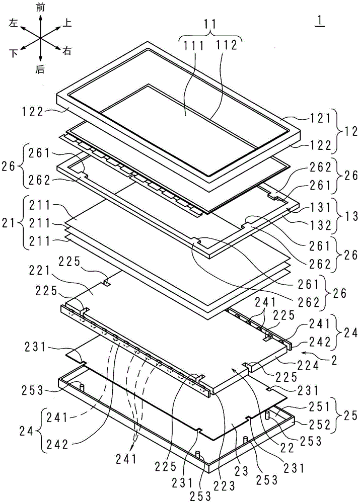
[0065] figure 1 It is an exploded perspective view schematically showing the structure of the display device 1 according to Embodiment 1 of the present invention.
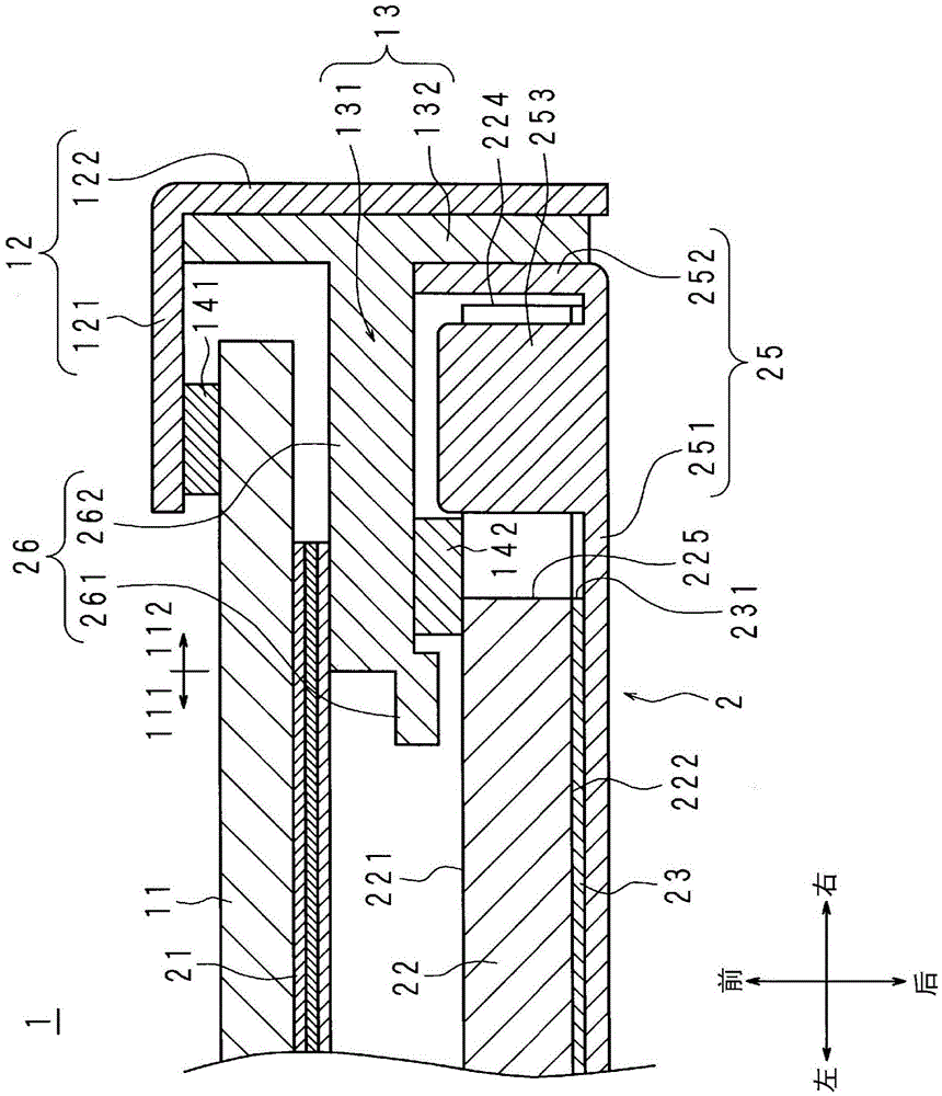
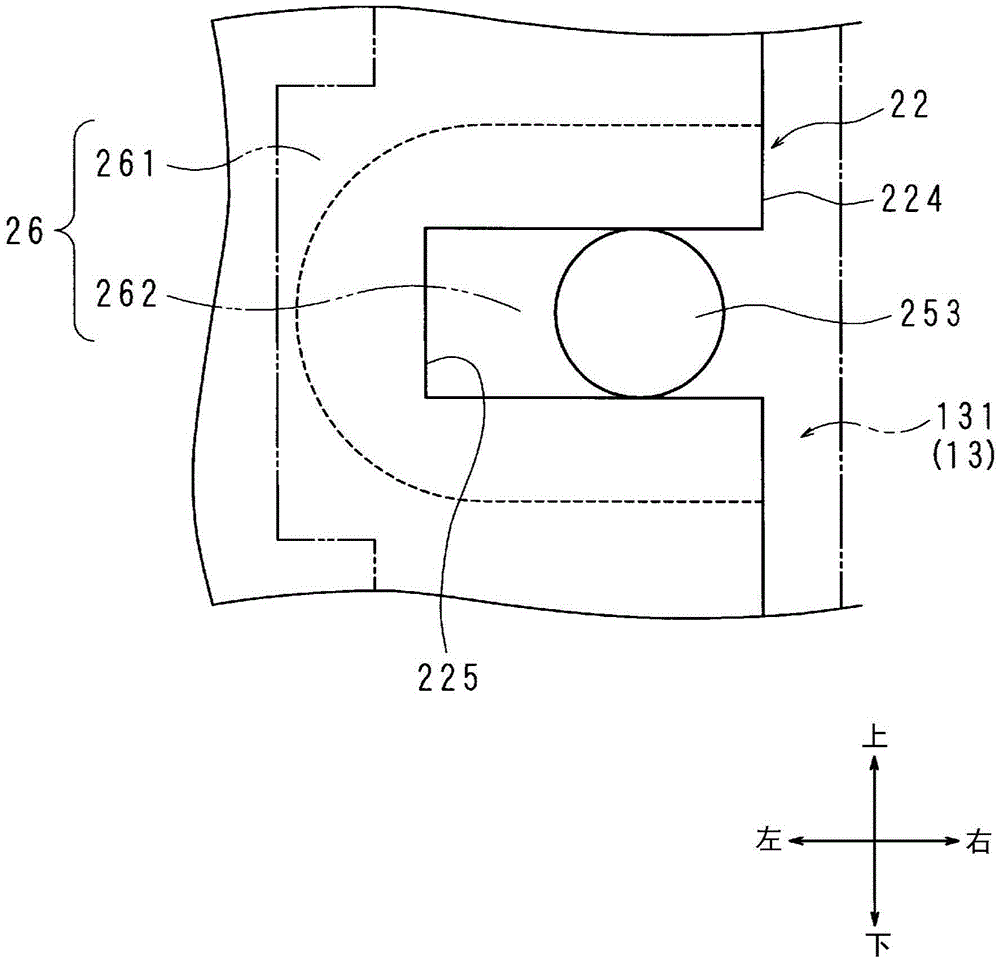
[0066] figure 2 as well as image 3 They are a horizontal cross-sectional view and a front view schematically showing the structure near the cover 26 included in the display device 1.

[0067] The display device 1 of this embodiment is, for example, a television receiver, an electronic billboard, a display for a personal computer, or the like.

[0068] First, the structure of the display device 1 will be described.

[0069] The display device 1 includes a display panel 11, a frame 12, a P frame (panel support portion) 13, a backlight unit (illumination device) 2, and a housing (not shown) that accommodates the above-mentioned components in a state where the display area 111 described later is exposed Wait.

[0070] The display panel 11 uses a liquid crystal display panel. The display panel 11 has a re...

Example Embodiment

[0122] Embodiment 2

[0123] Figure 4 It is a horizontal cross-sectional view schematically showing the structure of the vicinity of the cover 26 included in the display device 1 according to the second embodiment of the present invention. Figure 4 With embodiment 1 figure 2 Corresponding.

[0124] The display device 1 of this embodiment has substantially the same structure as the display device 1 of the first embodiment. In the following description, differences from Embodiment 1 will be described, and parts corresponding to Embodiment 1 will be given the same reference numerals, and their description will be omitted.

[0125] The display device 1 of this embodiment has a narrower frame than the display device 1 of the first embodiment. Therefore, as in the case of Embodiment 1, the frame area 112 of the display panel 11 is located on the front side of the front frame portion 131 of the P frame 13, but the display area 111 and the frame area 112 of the display panel 11 are locat...

Example Embodiment

[0127] Embodiment 3

[0128] Figure 5 It is a horizontal cross-sectional view schematically showing the structure in the vicinity of the cover 26 included in the display device 1 according to the third embodiment of the present invention. Figure 5 With embodiment 1 figure 2 Corresponding.

[0129] The display device 1 of this embodiment has substantially the same structure as the display device 1 of the first embodiment. Hereinafter, the differences from the first embodiment will be described. In addition, the same reference numerals are given to the parts corresponding to the first embodiment, and the description thereof will be omitted.

[0130] The P frame 13 of this embodiment is black (or gray). When the P frame 13 is black (or gray), each covering portion 26 is also black (or gray). The black (or gray) covering portion 26 has higher light-shielding properties than when the covering portion 26 is white.

[0131] The covering base end portion 262 of the covering portion 26 is...


PUM


Abstract

Provided are an illumination device and display device capable of even illumination. A positioning recess (225) provided in a light guide plate (22) and a portion in the periphery of the recess (225) are covered by a cover (26) from one surface side of the light-guide plate (22). As a result, the cover (26) suppresses the emission of light emitted from the vicinity of the recess (225) on the one surface of the light guide plate (22) onto the outer portion of a backlight unit (2) that functions as an illumination device. Thus, even if light is scattered at the recess (225) of the light guide plate (22) and the brightness of the vicinity of the recess (225) is greater than the brightness of other portions, the leaking of excessively bright light onto the outer portion of the backlight unit (2) (in this case, the side of a display panel (11)) is suppressed. That is, brightness unevenness caused by the recess (225) of the light guide plate (22) is suppressed.

Description

technical field [0001] The present invention relates to a lighting device and a display device having a light guide plate positioned by engagement of concave and convex. Background technique [0002] The liquid crystal display device includes a liquid crystal display panel for displaying images, and a backlight unit for illuminating the liquid crystal display panel from the rear side of the liquid crystal display panel. [0003] Next, a case where the liquid crystal display panel is arranged in an upright posture will be described. [0004] Conventionally, an edge-light type backlight unit has been proposed (see Patent Document 1). The edge-light type backlight unit has a rectangular light guide plate arranged via an optical sheet group on the back side of the liquid crystal display panel, a reflective sheet is arranged on the back side of the light guide plate, and the light source unit is arranged opposite to the lower end surface of the light guide plate. [0005] The l...

Claims


Application Information

Patent Timeline
IPC IPC(8): F21K9/20F21V17/00G02B6/00G02F1/1333G02F1/13357F21Y115/10
CPCG02B6/0088G02B6/002G02B6/0055
Inventor 杉本有正
Owner SAKAI DISPLAY PROD
Why Eureka
Try Eureka