Light diffusion sheet for overlaying, and backlight unit

A light diffusion sheet and backlight unit technology, applied in the direction of optical components, light guides, optics, etc., can solve the problems of slight roughness, unevenness, roughness, etc., and achieve the effect of suppressing flickering and uneven brightness

Active Publication Date: 2017-06-13
KEIWA INCORPORATED
View PDF3 Cites 12 Cited by
  • Summary
  • Abstract
  • Description
  • Claims
  • Application Information

AI Technical Summary

Problems solved by technology

[0006] However, it has been found that, if such a conventional top light-diffusing sheet is applied to a liquid crystal display device in which the miniaturization of the pixel pitch of a liquid crystal panel is promoted, there will be a problem with the s

Method used


Image

  • Light diffusion sheet for overlaying, and backlight unit
  • Light diffusion sheet for overlaying, and backlight unit
  • Light diffusion sheet for overlaying, and backlight unit

Examples


Embodiment approach

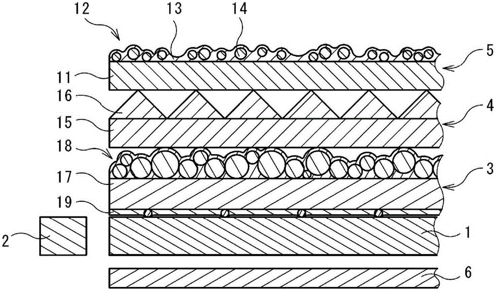
[0153] In addition, the light-diffusion sheet for top use of this invention, and a backlight unit can also be implemented in the aspect which modified and improved variously besides the said form. For example, the backlight unit may include another optical sheet other than the upper light diffusion sheet, the prism sheet, and the lower light diffusion sheet on the surface side of the light guide sheet. In addition, the backlight unit does not necessarily have to be an edge-type backlight unit, and may be, for example, a direct-type backlight unit in which a diffusion plate and a light source are arranged on the back side of a lower light-diffusing sheet.

[0154] The specific structures of the prism sheet, the light diffusion sheet, the light guide sheet, the light source and the reflection sheet of the backlight unit are not particularly limited, and members of various structures can be used.

[0155] The above light diffusion sheet is preferably a two-layer structure of a ba...

Embodiment 1

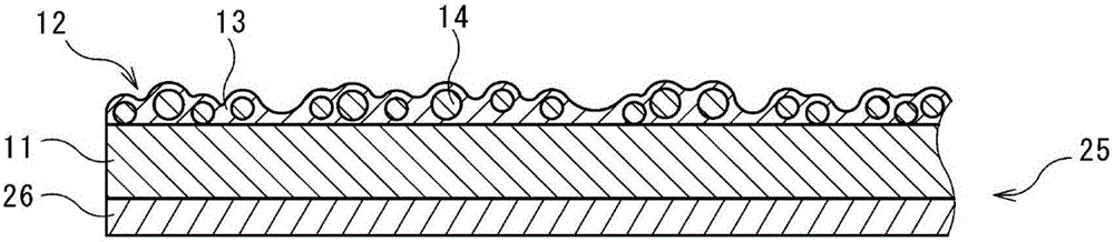
[0160] On the surface of a substrate layer with an average thickness of 75 μm mainly composed of polyethylene terephthalate, a light-diffusing layer in which resin beads are dispersed in a resin matrix mainly composed of an ultraviolet curable resin is laminated, thereby The top light-diffusing sheet of Example 1 was produced. As the resin beads, resin beads obtained by mixing first beads having a larger average particle diameter and second beads having a smaller average particle diameter than the first beads at a ratio of 2:1 (mass ratio) were used. In addition, the lamination amount of the light-diffusing layer is 2.5 g / m 2 The content rate of the resin matrix of the light-diffusion layer was 66.61 mass %, and the average thickness of the said light-diffusion layer was 3.5 micrometers. in addition, Figure 6 It is a partially enlarged cross-sectional photograph of the top light-diffusing sheet of Example 1.

Embodiment 2

[0162] Except having made content of the resin matrix of a light-diffusion layer into 52.57 mass %, it carried out similarly to Example 1, and manufactured the top light-diffusion sheet of Example 2. The average thickness of the light diffusion layer is 3.7 μm.


PUM

PropertyMeasurementUnit
Widthaaaaaaaaaa
The average particle sizeaaaaaaaaaa
Arithmetic mean roughnessaaaaaaaaaa

Abstract

The objective ofthe invention is to proivde a light diffusion sheet for overlaying, which can suppress uneven brightness due to shapes of bar-shaped prism portions projecting from a prism sheet on a back surface side, and can suppress flicker due to interference of a pixel distance of a liquid crystal panel. A light diffusion sheet for overlaying is to be provided on a front face side of a prism sheet in a backlight unit of a liquid crystal display device, and has a substrate layer and a light diffusion layer overlaid on a front face side of the substrate layer, in which the light diffusion layer contains a resin matrix and resin beads dispersed in the resin matrix, wherein: a mode diameter in a volume-weighted particle size distribution of the resin beads is no less than 2.5 [mu]m and no greater than 5.5 [mu]m; a density of the resin beads per unit area is no less than 9,000 beads/mm2 and no greater than 24,000 beads/mm2; and an average thickness of the light diffusion layer is no less than 2 [mu]m and no greater than 9 [mu]m. Preferably, the coefficient of variation of particle size of volume-weighted particle size distribution of the resin beads is no less than 42%.

Description

technical field [0001] The present invention relates to an upper light diffusion sheet and a backlight unit. Background technique [0002] Liquid crystal display devices are widely used as flat-panel displays by taking advantage of features such as thinness, light weight, and low power consumption, and their applications are expanding in mobile terminals such as televisions, personal computers, and smartphones, and portable information terminals such as tablet terminals. [0003] In such a liquid crystal display device, a backlight system in which a liquid crystal panel is illuminated from the rear side is widely used, and backlight units such as a side light type and a direct type are mounted. The side-light type backlight unit 101 of this liquid crystal display device is usually as follows: Figure 5 As shown, it is provided with: a light source 102; a square plate-shaped light guide plate 103 arranged with its end along the light source 102; a plurality of optical sheets ...

Claims


Application Information

Patent Timeline
IPC IPC(8): G02B5/02G02F1/13357
CPCG02B5/0242G02B5/0278G02F1/133615G02B5/0226G02B6/0051G02B6/0053G02B6/0061
Inventor 野中忠幸
Owner KEIWA INCORPORATED
Why Eureka
Try Eureka