
Driver device for an organic el passive matrix device

a passive matrix and drive device technology, applied in the direction of instruments, light sources, lighting apparatus, etc., can solve the problems of uneven luminance, excessively large reactive power, and large reactive power, and achieve the effect of suppressing uneven luminance, reducing power consumption, and low cos

Inactive Publication Date: 2008-11-27
FUJI ELECTRIC HLDG CO LTD
View PDF3 Cites 10 Cited by
  • Summary
  • Abstract
  • Description
  • Claims
  • Application Information

AI Technical Summary

Benefits of technology

[0017]The present invention provides a driver device for an organic EL passive matrix device that achieves reduction of power consumption and suppression of unevenness in luminance in the organic EL passive matrix device at a low cost.
[0023]The present invention provides such a driver device for an organic EL passive matrix device that achieves reduction in power consumption and suppression of uneven luminance by providing two row drivers at both ends of cathode lines, at a low cost by virtue of packaging a column driver and two row drivers in a single IC.

Problems solved by technology

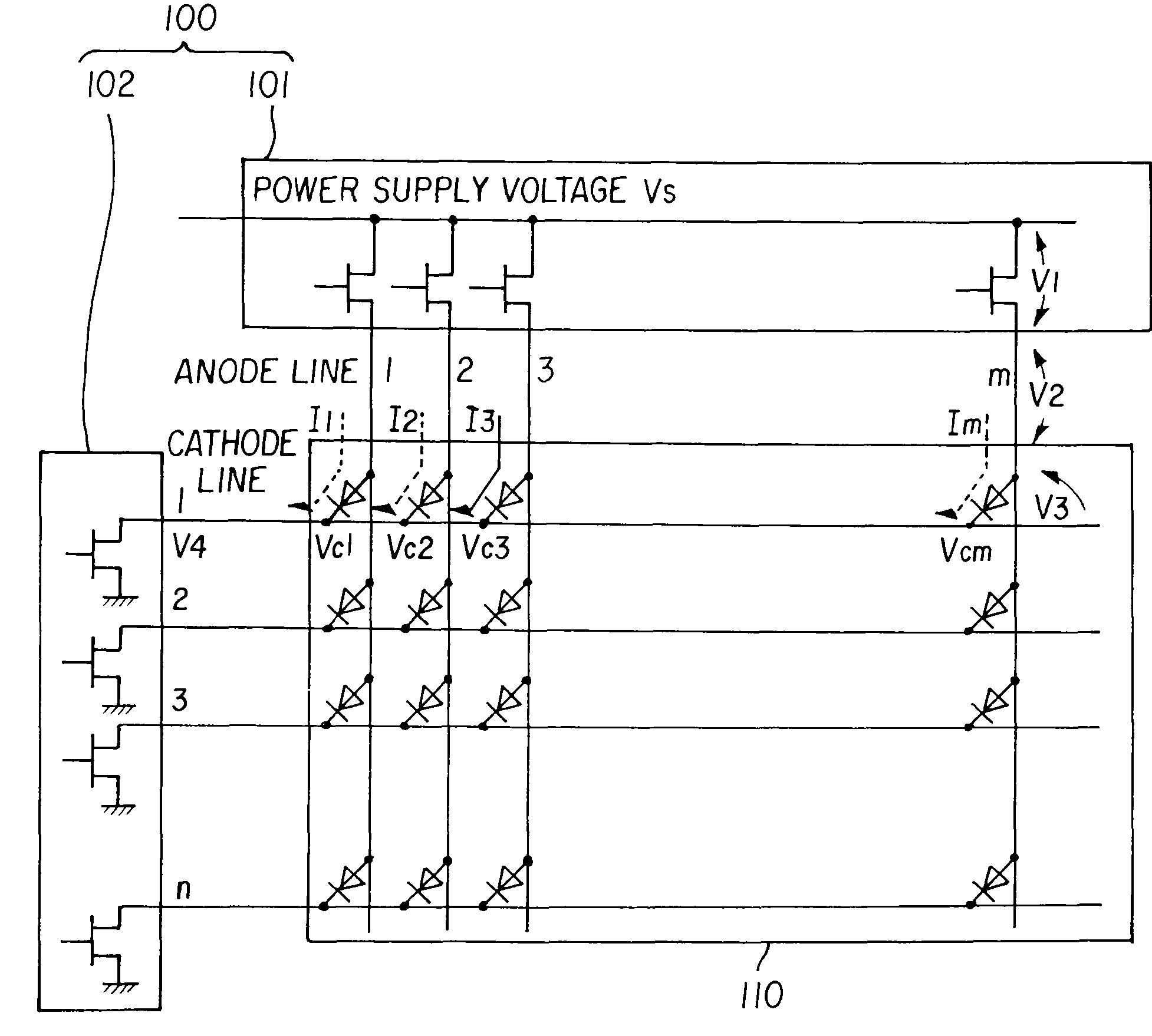
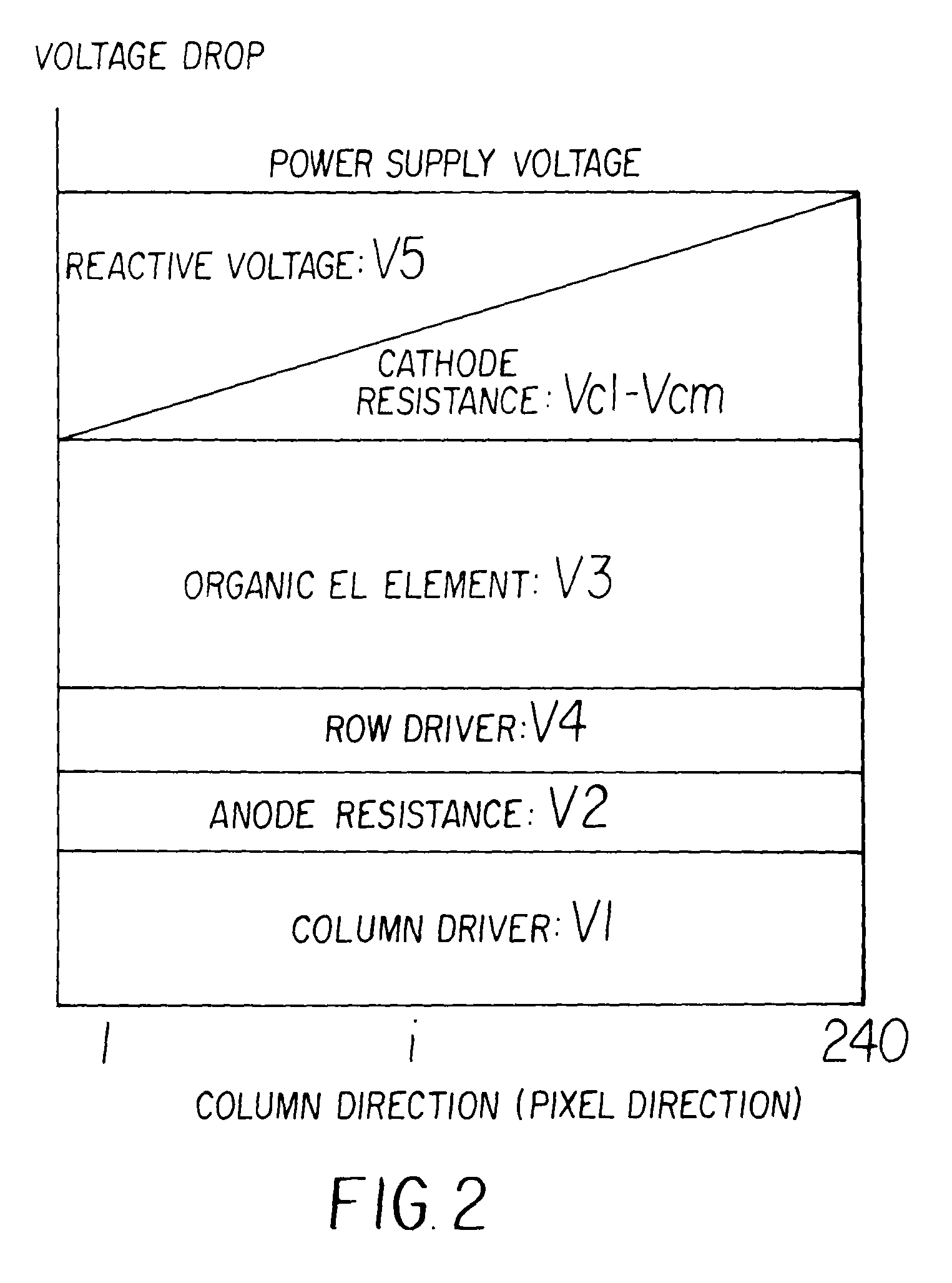
The reactive power grows so large that it cannot be ignored with expansion of the display area.
Thus, there exists a problem of excessively large reactive power in a generally employed driver device in which the driving current is sunk by a single row driver.
The variation of wiring resistance in the pixel direction causes a problem of unevenness of luminance in addition to the problem of power.
The variation in wire resistance causes variation in building-up characteristic at the pixels and variation in emitting time, resulting in the unevenness of luminance.
Enlargement of display area raises a problem of increased power consumption in addition to the problem caused by the wiring resistance.
This requires increase in current in order to ensure desired luminance, causing increase in power consumption in the organic EL elements.

Method used


Image

  • Driver device for an organic el passive matrix device
  • Driver device for an organic el passive matrix device
  • Driver device for an organic el passive matrix device

Examples


example 1

[0032]FIG. 5 shows a driver device for an organic EL passive matrix device of a first embodiment example according to the invention. The driver device 500 drives an organic EL passive matrix device 510 having m columns and n rows. The driver device500 comprises a column driver 501, a first row driver 502, a second row driver 503, a memory 504, and a power supply / control signal input 505. An anode of each organic EL element of the organic EL passive matrix device 510 is connected to an output of the column driver 501, and cathodes of each row are connected to inputs of the row drivers 502 and 503.

[0033]The power supply / control signal input 505 accepts a power and a control signal from outside and feeds the power and the signal to the column driver 501, the first row driver 502, the second row driver 503, and the memory 504. The power and the signal are, for example, a power supply voltage Vs for the column driver 501 and write-in display data for the memory 504.

[0034]The driver devic...

example 2

[0037]FIG. 7 shows a driver device for an organic EL passive matrix device of a second embodiment example according to the invention. The driver device 700 comprises a first partial driver device 710 that is a device of Example 1, a second partial driver device 720 that is another device of Example 1, and a connector 730 connecting the first partial driver device 710 and the second partial driver device 720. The first and second partial driver devices 710 and 720 are disposed at both ends of anode lines of an organic EL passive matrix device 740 and drive the organic EL passive matrix device 740 separately in two sections in synchronism with each other through the connector 730.

[0038]The power supply / control signal inputs 715 and 725 accept a power and a control signal from outside and feeds the power and the signal to the column drivers 715 and 725, respectively. Driver device 710 includes two row drivers 712 and 713. Likewise, driver device 720 includes two row drivers 722 and 723...


PUM


Abstract

A driver device is provided for an organic EL passive matrix device that achieves reduction in power consumption and suppression of uneven luminance at a low cost. The driver device includes a column driver, a first row driver, a second row driver, a memory, and a power supply / control signal input. An anode of each organic EL element of the organic EL passive matrix device is connected to an output of the column driver, and cathodes in a row are connected together to an input of the row driver. In the driver device, the column driver is disposed in the vicinity of one peripheral side of the IC, and each of the row drivers is disposed in the vicinity of one of the two peripheral sides adjacent to the peripheral side at which the column driver is disposed. These three drivers are packaged on a single integrated chip (IC) chip.

Description

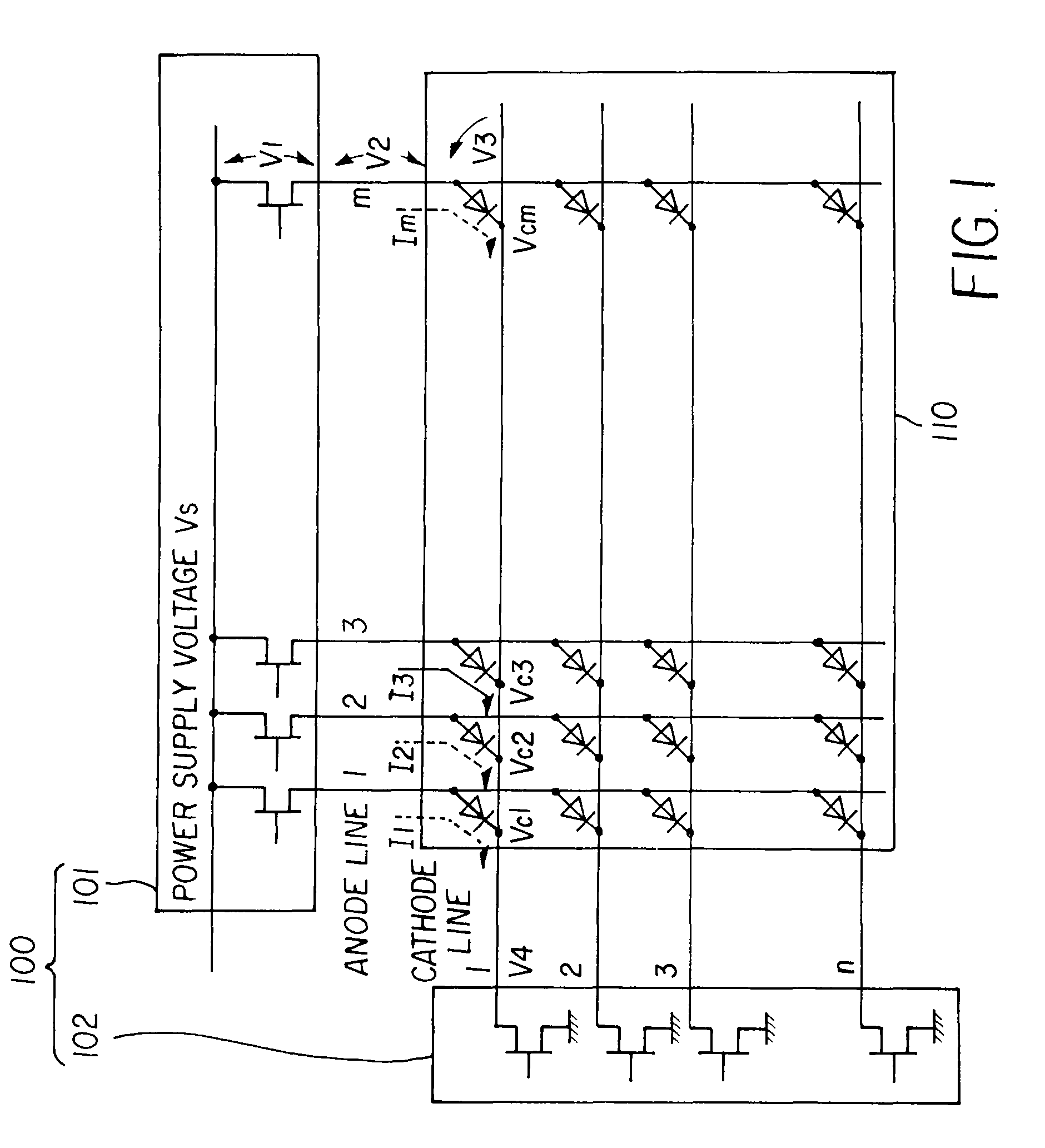
CROSS-REFERENCE TO RELATED APPLICATION[0001]This application is based on, and claims priority from, Japanese Patent Application No. 2007-135856, filed on May 22, 2007, the contents of which are incorporated herein by reference.BACKGROUND[0002]The present invention relates to a driver device for an organic EL passive matrix device, and in particular, to a driver device having two row drivers, for an organic EL passive matrix device.[0003]Organic EL devices are expected to be applied to next generation displays. A passive matrix system is one of driving systems to make an organic EL device to emit light. The system composes a matrix of electrode lines in rows and columns and drives organic EL elements (corresponding to pixels) arranged on points of intersection of the lines.[0004]FIG. 1 shows a driver device generally employed for driving an organic EL device 110 in the passive matrix system (hereinafter referred to as an organic EL passive matrix device). The driver device 100 is pro...

Claims


Application Information

Patent Timeline
IPC IPC(8): G09G3/30
CPCG09G3/3216G09G2310/0221G09G2310/0278G09G2320/0223G09G2320/0233G09G2330/021G09G3/20G09G3/30G09G3/32H05B33/12
Inventor TSUJI, NOBUHIKO
Owner FUJI ELECTRIC HLDG CO LTD
Learn More