Lighting apparatus and image display apparatus provided therewith

A technology for lighting devices and light sources, which is applied to cooling/heating devices, lighting devices, lighting and heating equipment of lighting devices, etc., can solve problems such as the decline of heat dissipation performance, improve heat dissipation performance, suppress uneven heat distribution, and heat conduction. good performance

Inactive Publication Date: 2013-03-27
SHARP KK
View PDF9 Cites 13 Cited by
  • Summary
  • Abstract
  • Description
  • Claims
  • Application Information

AI Technical Summary

Problems solved by technology

As a result, there is a problem of degraded thermal performance

Method used


Image

  • Lighting apparatus and image display apparatus provided therewith
  • Lighting apparatus and image display apparatus provided therewith
  • Lighting apparatus and image display apparatus provided therewith

Examples


Embodiment approach 1

[0089] (I) Structure of the lighting device of this embodiment

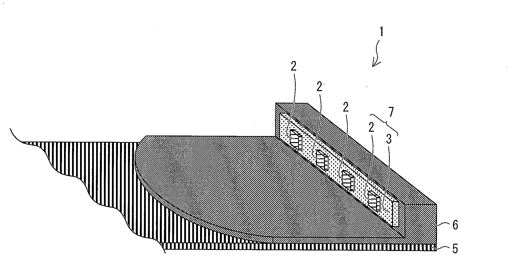
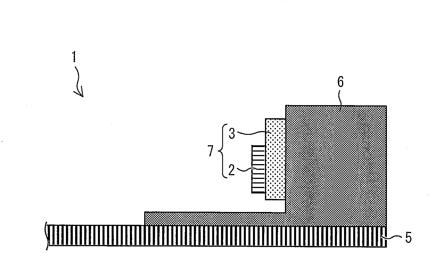
[0090]The lighting device of this embodiment includes: a light source; a light guide member having a light incident surface and a light exit surface perpendicular to the light incident surface; Opposite: a thermally conductive component, which is used to transmit the heat generated by the above-mentioned light source to the above-mentioned heat dissipation component. The heat conductive member has a light source holding portion formed adjacent to each other, the light source holding portion has a surface facing the light incident surface, and a plate-shaped portion has a surface facing the light emitting surface and a plate-shaped portion that is connected to the heat dissipation surface. The surface facing the component; the light source is disposed on the light incident surface of the light source holding part facing the light incident surface; the surface of the plate-shaped part facing the heat dissipation me...

Embodiment approach 2

[0145] based on the following Figure 10 as well as Figure 11 This embodiment will be described. For convenience of explanation, the same reference numerals are assigned to the illustrated components having the same functions as those in the first embodiment described above, and their descriptions are omitted. In addition, the description of terms used in Embodiment 1 above is omitted.

[0146] (I) Structure of the lighting device of this embodiment

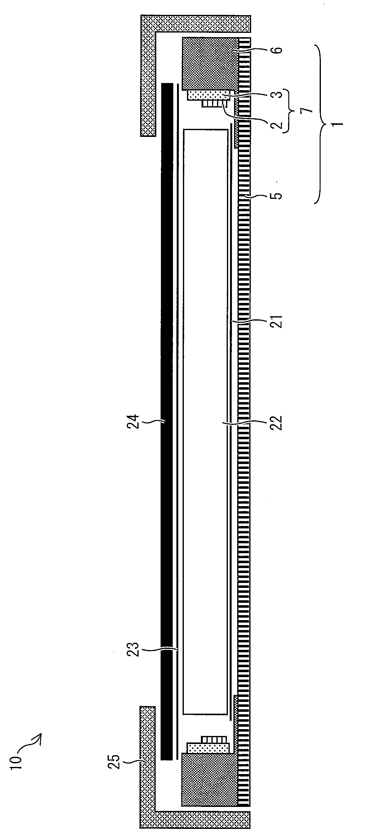
[0147] Compared with the lighting device of Embodiment 1 described above, in the lighting device of this embodiment, the "heat spreader" 6 is not a "component formed integrally with the frame 17 and the heat conduction plate 16", but "a component formed by the frame 17 and the heat conduction plate 16." independent parts of each other".

[0148] Figure 10 It is a schematic cross-sectional configuration diagram of a liquid crystal display device (image display device) 10 including a backlight device (illumination device) 1 ...

Embodiment approach 3

[0166] based on the following Figure 12 to Figure 15 This embodiment will be described. For convenience of explanation, the same reference numerals are assigned to the illustrated components having the same functions as those in the first embodiment described above, and their descriptions are omitted. In addition, the description of terms used in Embodiment 1 above is omitted.

[0167] (I) Structure of the lighting device of this embodiment

[0168] Compared with the lighting device of the above-mentioned first embodiment, the lighting device of this embodiment further includes a reinforcing member for reinforcing the "heat spreader 6".

[0169] Figure 12 It is a schematic cross-sectional configuration diagram of a liquid crystal display device (image display device) 10 including a backlight device (illumination device) 1 according to this embodiment. Figure 13 The shape of the heat spreader 6 of this embodiment is expressed.

[0170]

[0171] The reinforcing member ...


PUM

PropertyMeasurementUnit
thermal conductivityaaaaaaaaaa
lengthaaaaaaaaaa
thermal conductivityaaaaaaaaaa

Abstract

Provided is a lighting apparatus and an image display apparatus provided therewith, wherein heat dissipation capability can be improved while maintaining structural strength, uneven brightness generated due to uneven heat distribution can be inhibited, and the image display apparatus can be made to be thinner. In a heat conductive member (6), a light-source holding section, which has a face facing a light-entering face of a light-guiding member, and a plate-formed section, which has a face facing a light-exiting face of the light-guiding member and a face facing a heat dissipation member (5), are formed adjacent to each other. At the light-source holding section, a light source (7) is arranged on the face facing the light-entering face of the light-guiding member, in a direction facing towards the light-entering face, and the face of the plate-formed section facing the heat dissipation member (5) is made to come in contact with the face of the heat dissipation member (5) facing the light-guiding member. At the plate-formed section, the center of gravity of the plate-formed section is biased in both a direction parallel to the light-entering face and a direction parallel to the light-exiting face.

Description

technical field [0001] The present invention relates to an illumination device used in an image display device such as a liquid crystal display device. Background technique [0002] These image display devices such as liquid crystal display devices generally include: a display panel that can control the brightness, chromaticity, etc. of pixels; a backlight device (illumination device) that irradiates light to the display panel; Circuits and circuit substrates. [0003] The backlight device diffuses light in the image display device to surface-emit light toward the display panel. There are two types of backlight devices: the direct type, in which the light sources are distributed on the back side of the backlight device; and the side-light type, in which the light sources are installed so that light enters from the side of the backlight device (also called "side-light"). Compared with the direct-type type, the edge-light type can design the thickness of the backlight device...

Claims


Application Information

Patent Timeline
Patent Type & Authority Applications(China)
IPC IPC(8): F21S2/00F21V29/00G02F1/1333G02F1/13357F21Y101/02
CPCG02F2001/133628G02F1/133615G02B6/0085F21V29/20G02F1/133628
Inventor 神田浩文住川雅人高山武史酒井宏祐森圭子
Owner SHARP KK
Why Eureka
Try Eureka