Light guiding plate, surface light source device, display device, and electronic device

A technology of a light guide plate and a surface light source is applied in the field of surface light source devices, display devices, electronic equipment, and light guide plates, and can solve the problem of uneven brightness of liquid crystal display devices.

Active Publication Date: 2019-06-04
NICHIA CORP
View PDF6 Cites 10 Cited by
  • Summary
  • Abstract
  • Description
  • Claims
  • Application Information

AI Technical Summary

Problems solved by technology

In the case of a direct type backlight, a plurality of LEDs are arranged directly under the liquid crystal display device, but the liquid crystal display device is prone to uneven brightness in the part directly above the LED and other parts

Method used


Image

  • Light guiding plate, surface light source device, display device, and electronic device
  • Light guiding plate, surface light source device, display device, and electronic device
  • Light guiding plate, surface light source device, display device, and electronic device

Examples


Embodiment approach 1

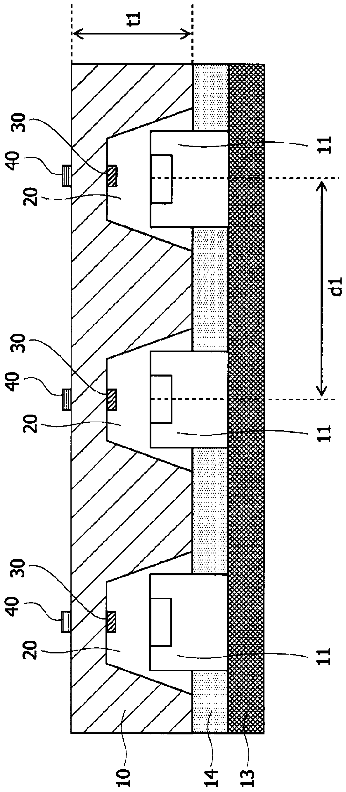
[0048] Figure 3A is a cross-sectional view schematically showing the light guide plate 10 . The light guide plate 10 has a plurality of recesses 20 on the lower surface of the light guide plate 10 . That is, the concave portion 20 is a concave portion that opens below the light guide plate 10 and is depressed upward. Furthermore, a plurality of light sources 11 are arranged on the mounting substrate 13 , and one light source 11 is accommodated in each recess 20 . In addition, the recessed part 20 is also called a storage part. Furthermore, the light emitted from the light source 11 enters the light guide plate 10 . The light incident into the light guide plate 10 is refracted, reflected and diffused in the light guide plate 10 and emitted from the light exit surface of the light guide plate 10 , so that the light exit surface of the light guide plate 10 emits light uniformly. The thickness (height) t1 of the light guide plate 10 and the distance d1 between the light sourc...

Embodiment approach 2

[0054] Figure 4 It is a cross-sectional view schematically showing the light guide plate 10 of the second embodiment. The size ratio and the like of each component are not limited to the illustrated examples. In the present embodiment, components corresponding to the above-described configurations are given corresponding symbols and descriptions thereof are omitted.

[0055] The light guide plate 10 of this embodiment also has two direction changing portions. Specifically, there is a first direction changing portion 30 at the inner end of the concave portion 20 near a line passing through the light source 11 and perpendicular to the light emitting surface. Furthermore, between the diffusion sheet 15 and the prism sheet 16 , there is a second direction changing portion 40 in the vicinity of the vertical foot of the vertical line hanging from the light source 11 to the diffusion sheet 15 or the prism sheet 16 . Summarizing Embodiment 1 and Embodiment 2, the first direction c...

Embodiment approach 3

[0058] Figure 5 It is a cross-sectional view schematically showing the light guide plate 10 of the third embodiment. The size ratio and the like of each component are not limited to the illustrated examples. In the present embodiment, components corresponding to the above-described configurations are given corresponding symbols and descriptions thereof are omitted.

[0059] Figure 5 The concave portion 20 is a truncated conical depression provided on the light guide plate 10, and is formed as a through hole. Also, the diameter of the recess 20 becomes narrower from the opening on the lower surface side toward the opening on the upper surface side. That is, the housing portion of the light source 11 of the present embodiment is formed with a tapered through-hole on its side surface.

[0060] In addition, a light diffusion layer 50 formed of a diffusion material for diffusing light is provided on the light emitting surface side (upper surface side) of the light guide plate...


PUM


Abstract

Provided is a technology for promoting reduction in thickness of a light guiding plate and inhibiting luminance unevenness of a light guiding plate. This light guiding plate is provided with: a recessprovided opposite to a light emitting surface that emits light; a first direction changing portion that is provided inside the recess and upward toward the light emitting surface with respect to a light emitting element provided opposite to the light emitting surface and that changes the traveling direction of at least a part of light of the light emitting element; and a second direction changingportion that is provided upward of the light emitting element and above the light emitting surface and that changes the traveling direction of at least a part of light from the light emitting element.

Description

technical field [0001] The invention relates to a light guide plate, a surface light source device, a display device and electronic equipment. Background technique [0002] As the form of a backlight for a liquid crystal display device, there are a form called an edge-light type backlight and a form called a direct-type backlight. As a display for a large liquid crystal display device, a direct type backlight is used which has high light utilization efficiency and is easy to increase brightness. In addition, as a light source of the backlight, for example, LEDs (Light Emitting Diodes) that emit white light are used. In the case of a direct type backlight, a plurality of LEDs are arranged directly under the liquid crystal display device, but the liquid crystal display device tends to have uneven brightness in the part directly above the LED and other parts. [0003] Conventionally, the following surface light source device has been proposed: the surface light source device ...

Claims


Application Information

Patent Timeline
Patent Type & Authority Applications(China)
IPC IPC(8): G02F1/13357G02B6/00
CPCF21S2/00F21V5/04H01L33/00G02B6/0021G02B6/0053G02F1/133603G02F1/133606G02B6/0016G02B6/0036G02B6/0043G02F1/133607G02B3/08G02B6/0051G02B26/08G02F1/1335G02F1/133524G02B6/0028G02F1/133611G02F1/133605G02F2201/305G02B6/0018G02B6/0055G02B6/0031G02B6/0025G02B6/003G02B6/0073
Inventor 渡边正太郎石见直树伊藤嘉则下田知数
Owner NICHIA CORP
Why Eureka
Try Eureka