Lens drive device, spring member and manufacturing methods therefor

A technology of a lens driving device and a spring component, applied in the field of spring components, can solve problems such as difficulty in controlling the spring constant, and achieve the effects of preventing the design space from being narrowed, high precision, and promoting thinning

Inactive Publication Date: 2009-05-20
NIDEC SANKYO CORP
View PDF2 Cites 19 Cited by
  • Summary
  • Abstract
  • Description
  • Claims
  • Application Information

AI Technical Summary

Problems solved by technology

However, especially for the lens driving device, as the device becomes smaller and thinner, the spring member is required t

Method used


Image

  • Lens drive device, spring member and manufacturing methods therefor
  • Lens drive device, spring member and manufacturing methods therefor
  • Lens drive device, spring member and manufacturing methods therefor

Examples


Embodiment Construction

[0078] The best mode for carrying out the present invention will be described below with reference to the drawings.

[0079] [Mechanical structure]

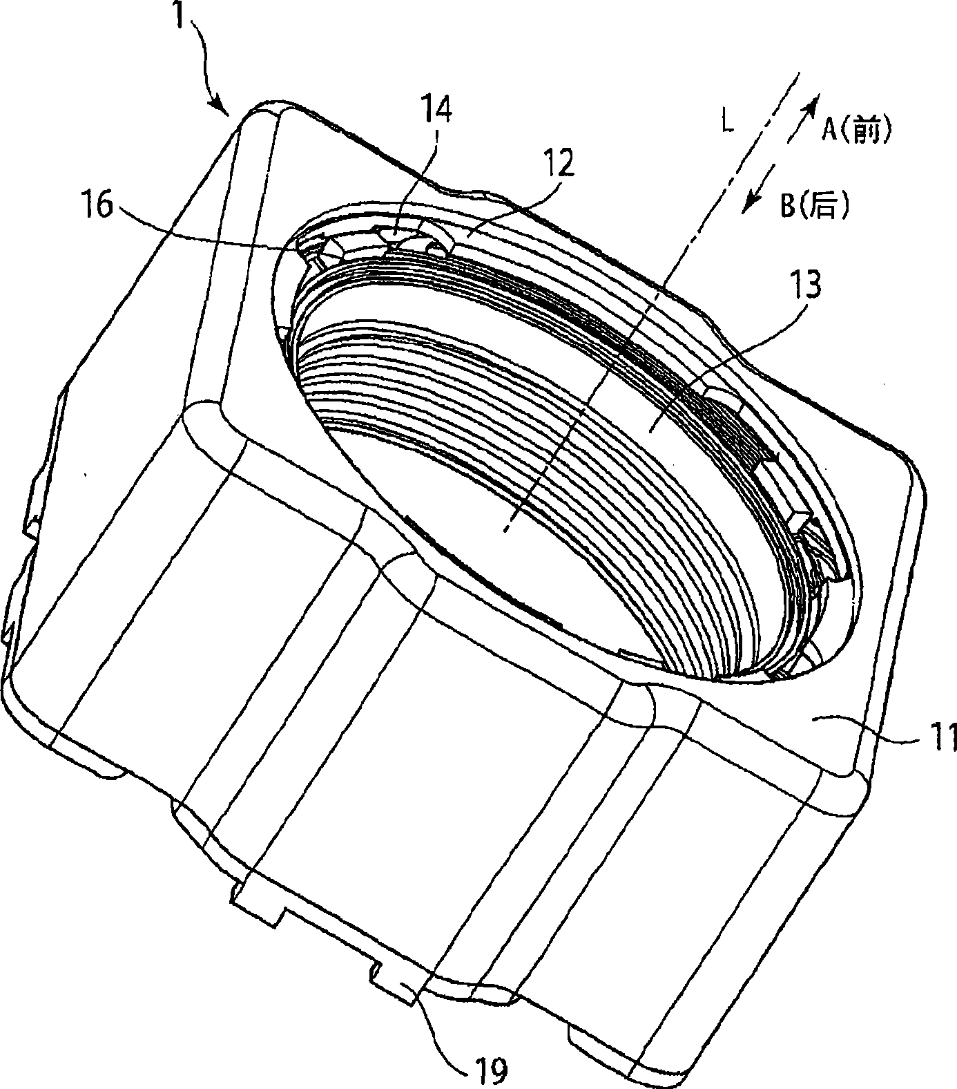
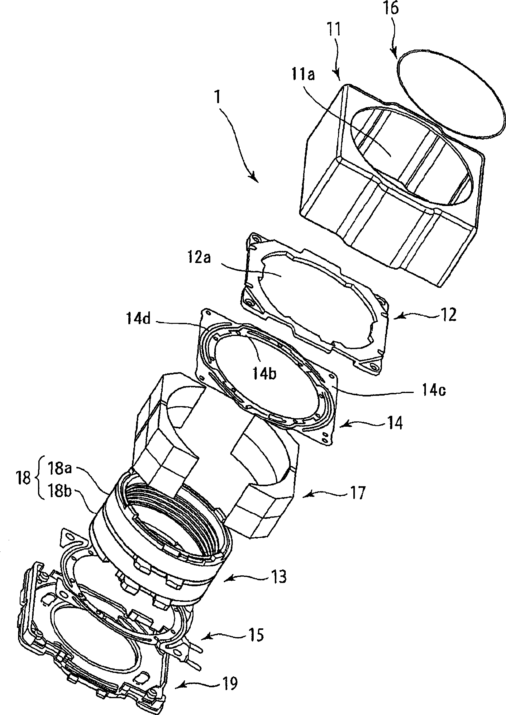
[0080] figure 1 It is a perspective view showing the external structure of the lens driving device 1 according to the embodiment of the present invention. figure 2 It is an exploded perspective view showing the mechanical structure of the lens driving device 1 according to the embodiment of the present invention.

[0081] exist figure 1 and figure 2 Among them, the lens driving device 1 has: a yoke 11, a cover 12, a sleeve 13, a first leaf spring 14, a second leaf spring 15, a wire spring 16, a magnet 17, a coil 18 (the first coil 18a and the second coil 18b ), and holder 19.

[0082] In addition, the lens barrel on which the lens is mounted is not shown. The lens driving device 1 directs the sleeve 13 toward the A direction (front side) close to the object (image capturing object) and the B direction (rear side) close to...


PUM


Abstract

A lens drive device, spring member and manufacturing method thereof prevents narrow space of soldering tin of part wherein braze welding is implemented in a designed space to accelerate the device to be slim. The lens drive device (1) includes a movable body (sleeve 13) movable in an optical axis direction, a support body (maintaining element 19) supporting the movable body through a spring member and a magnetic drive mechanism having a coil (18) on the movable body and driving the movably body along the optical axis, the spring element (second plate spring) which may include spring pieces (15A, 15B) electrically separated from each other, formed with a coil connecting part (15e) to which one of a winding start part and a winding end part of the coil is electrically connected. The movablebody is provided with an accommodating part (13b) for accommodating the coil connecting part (15e) bended.

Description

technical field [0001] The invention relates to a lens driving device which drives a lens to displace along an optical axis to image an object. In addition, the present invention relates to a lens drive device that supports a movable body having a lens in a displaceable form in the optical axis direction by a spring member, a spring member having a leaf spring-shaped arm, and a method for manufacturing the same. Background technique [0002] In recent years, along with the popularization of mobile phones with cameras equipped with cameras, opportunities to use such mobile phones to photograph various subjects are increasing. For example, you may shoot a subject that is a certain distance from the camera lens, such as a friend or a landscape (normal shooting), or take a picture of a subject that is close to the camera lens, such as a bus timetable or flower petals ( low magnification). [0003] In macro shooting, the lens position of the camera needs to be located slightly ...

Claims


Application Information

Patent Timeline
IPC IPC(8): G02B7/04H02K33/18
Inventor 须江猛樋口大辅武居勇一古谷幸男南泽伸司
Owner NIDEC SANKYO CORP
Why Eureka
Try Eureka