Planar illumination device and display device provided with the same

A lighting device and planar technology, which is applied to lighting devices, lighting and heating equipment, point light sources, etc., can solve the problems of decreased light utilization rate, increased light loss, thinning of planar lighting devices, etc., and achieves improved utilization. efficiency, and the effect of improving the utilization rate of light

Inactive Publication Date: 2012-01-18
SHARP KK
View PDF1 Cites 14 Cited by
  • Summary
  • Abstract
  • Description
  • Claims
  • Application Information

AI Technical Summary

Problems solved by technology

Therefore, it is difficult to reduce the thickness of the planar lighting device 2020 and the display device 2001, and it is difficult to reduce the manufacturing cost.
[0007] In addition, in the display device 2001 of a conventional example, the light emitted from the light guide plate 2022 passes through a plurality of optical sheets 2023, so the loss of light when passing through each optical sheet 2023 increases.
Therefore, there is also a disadvantage such as a decrease in light utilization efficiency.

Method used


Image

  • Planar illumination device and display device provided with the same
  • Planar illumination device and display device provided with the same
  • Planar illumination device and display device provided with the same

Examples


no. 1 approach

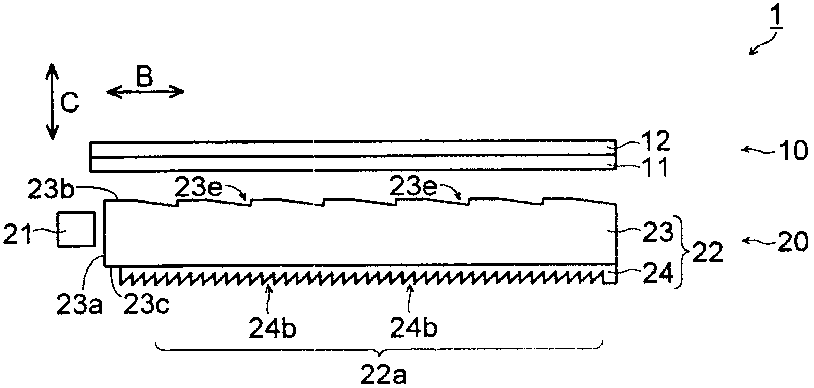
[0153] First, refer to Figure 1 to Figure 6 The structure of the liquid crystal display device 1 including the backlight device 20 according to the first embodiment of the present invention will be described.

[0154] like figure 1 As shown, the liquid crystal display device 1 according to the first embodiment of the present invention includes: a liquid crystal display panel 10; a backlight device 20 disposed on the back side of the liquid crystal display panel 10; and a frame ( not shown). In addition, the liquid crystal display device 1 is an example of the "display device" of the present invention, and the liquid crystal display panel 10 is an example of the "display panel" of the present invention. In addition, the backlight device 20 is an example of the "planar lighting device" of the present invention.

[0155] The liquid crystal display panel 10 includes an AM substrate (active matrix substrate) 11 ; a counter substrate 12 arranged opposite to the AM substrate 11 ...

no. 2 approach

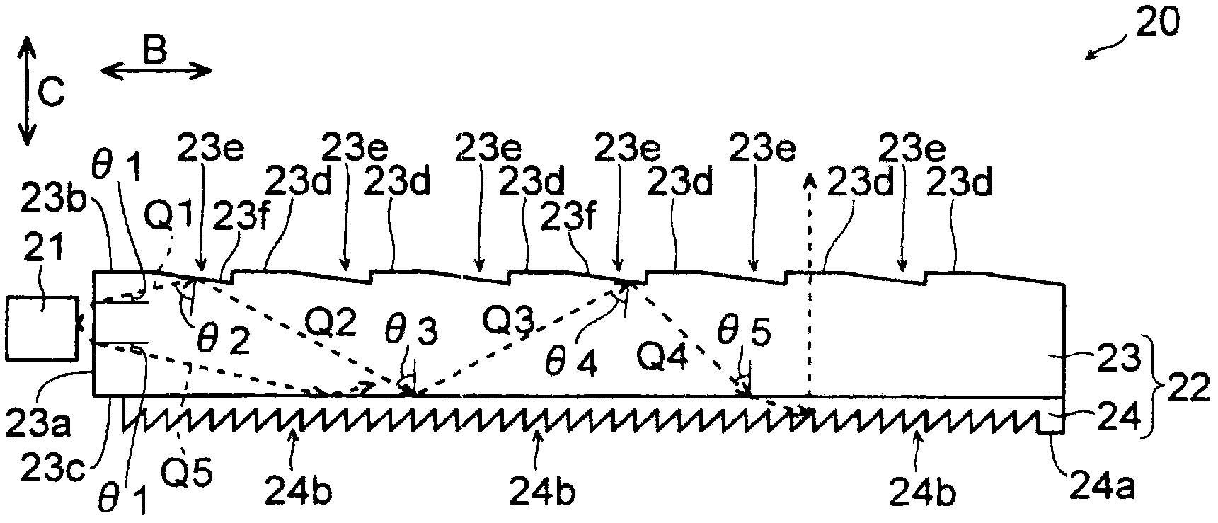
[0240] In this second embodiment, refer to Figure 19 and Figure 20 A case where the prism 123e is formed on the back surface 123c of the light guide body 123, which is different from the above-described first embodiment, will be described.

[0241] In the backlight device 120 of the second embodiment of the present invention, as Figure 19 As shown, the light guide plate 122 is formed of a light guide body 123 having a light incident surface 123 a on which light from the LED 21 is incident, and a low refractive index layer 124 having a refractive index smaller than that of the light guide body 123 . In addition, the backlight device 120 is an example of the "planar lighting device" of the present invention, and the light guide plate 122 is an example of the "light guide member" of the present invention.

[0242] The light guide body 123 of the second embodiment has a shape obtained by inverting the light guide body 23 of the first embodiment described above in the C direct...

no. 3 approach

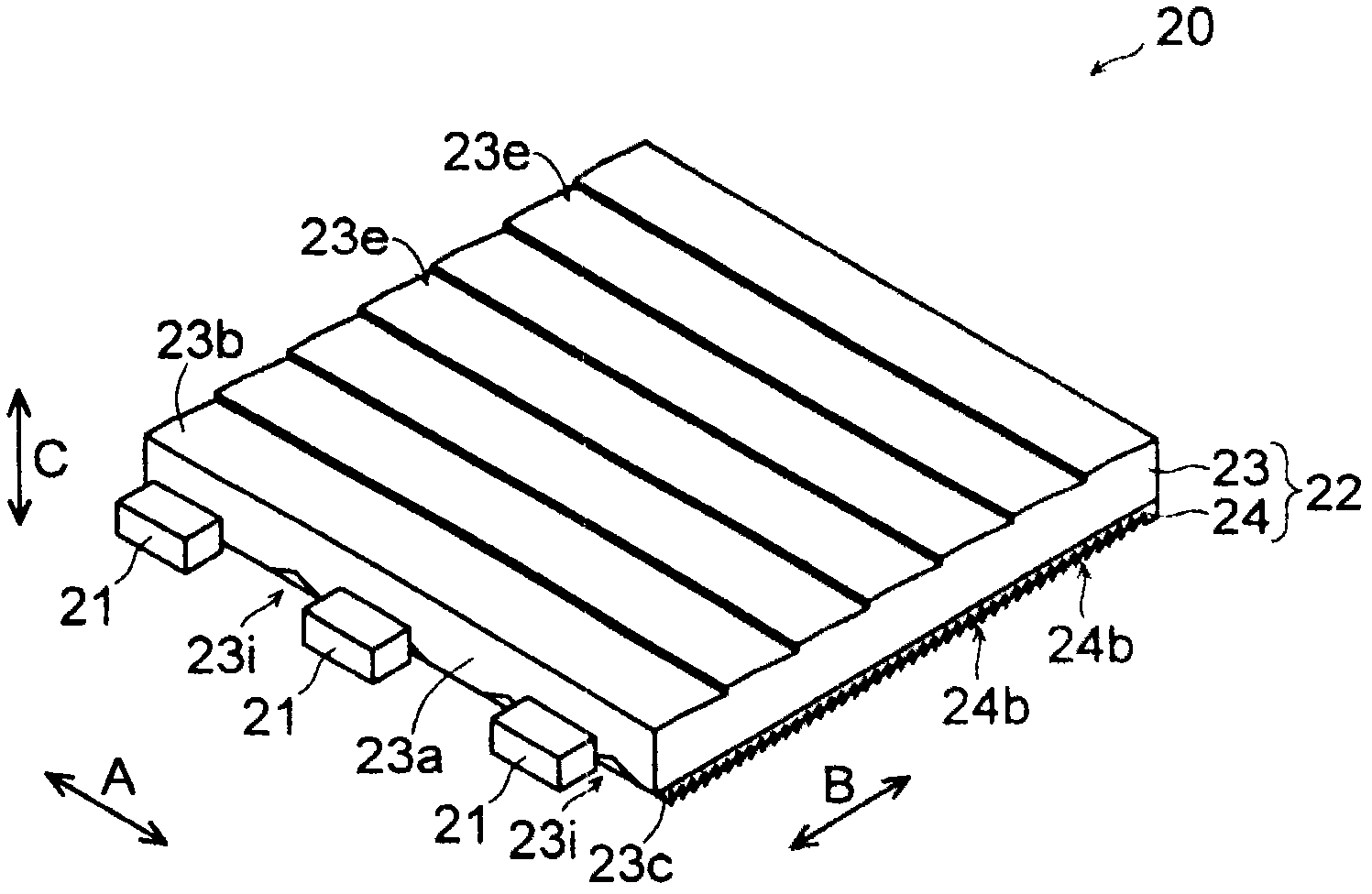
[0253] In this third embodiment, refer to Figure 21 to Figure 23 The case where prisms 223e and 223i are formed on the light exit surface 223b of the light guide body 223, which is different from the first and second embodiments described above, will be described.

[0254] In the backlight device 220 of the third embodiment of the present invention, as Figure 21 and Figure 22 As shown, the light guide plate 222 is formed of a light guide body 223 having a light incident surface 223 a on which light from the LED 21 is incident, and a low refractive index layer 224 having a refractive index smaller than that of the light guide body 223 . In addition, the backlight device 220 is an example of the "planar lighting device" of the present invention, and the light guide plate 222 is an example of the "light guide member" of the present invention.

[0255] In the third embodiment, as Figure 22 As shown, a plurality of flat portions 223d and a plurality of concave prisms 223e ar...


PUM

PropertyMeasurementUnit
thicknessaaaaaaaaaa
refractive indexaaaaaaaaaa

Abstract

Provided is a planar illumination device wherein the use efficiency and the brightness of light are improved while suppressing the unevenness of the brightness; the increase of the manufacturing cost is suppressed; and the thickness of the planar illumination device can be reduced. In the planar illumination device (backlight device) (20), a plurality of prisms which gradually reduce the incident angle of light with respect to the back surface (23c) of the light guiding element are provided on a light emitting surface (23b) of a light guiding element (23). A plurality of prisms (24b) are formed on a back surface (24a) of a low refractive index layer (24). The prisms (24b) reflect all of the light emitted from a LED (21) at the interface between the back face of the low refractive index layer and an air layer.

Description

technical field [0001] The present invention relates to a planar lighting device and a display device including the same, and particularly to a planar lighting device including a light guide member and a display device including the same. Background technique [0002] Conventionally, a display device including a planar lighting device including a light guide member has been known. Figure 78 It is a side view showing the structure of a conventional display device. like Figure 78 As shown, a conventional display device 2001 includes: a display panel 2010; [0003] The planar illuminating device 2020 is an edge-light illuminating device including: a plurality of LEDs (light emitting diodes) 2021 arranged in a predetermined direction (direction perpendicular to the paper surface); and a light guide plate that guides light from the LEDs 2021 2022 ; a plurality of optical sheets 2023 arranged on the side of the light exit surface 2022a of the light guide plate 2022 ; [0004] ...

Claims


Application Information

Patent Timeline
Patent Type & Authority Applications(China)
IPC IPC(8): F21S2/00G02F1/13357F21Y101/02
CPCG02B6/0055G02B6/0053G02B6/0038
Inventor 石田壮史甲斐田一弥川村忠史八代有史门胁真也国政文枝重田博昭结城龙三
Owner SHARP KK
Why Eureka
Try Eureka