
Combined suppression method of ISI and phase noise in TDS-OFDM communication system
A phase noise and time-domain signal technology, applied in the field of ISI and phase noise suppression, can solve the problems of demodulation result deterioration, channel delay, interference estimation and elimination, etc.
- Summary
- Abstract
- Description
- Claims
- Application Information
AI Technical Summary
Problems solved by technology
Method used
Image

Examples
Embodiment
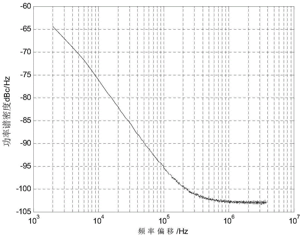
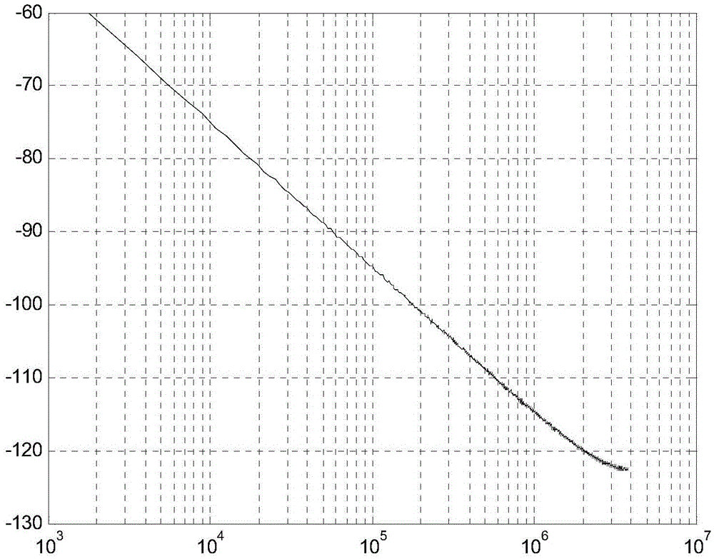
[0097] With the number of DFT points N=3780, 64QAM modulation mode, the PN sequence mode used is 420 points PN sequence mode. The phase noise modes are Gaussian color noise model and Wiener phase noise model respectively, and the receiving end performs the above steps 1 to 6 in turn to obtain the final result for demodulation processing The ideal estimation of the channel response of the two multipath channels is as follows: Figure 9 , 10 shown. The receiving end executes steps 2 and 3, and the constellation diagram after channel equalization is as follows Figure 11 shown. After the receiving end executes step 4, the obtained constellation diagram is as follows Figure 12 shown. Figure 13 For the initial (primary) estimate of the phase noise, the comparison between the second phase noise estimate and the actual phase noise shows the difference between the two phase noise estimates. Figure 14 In order to check the channel conditions, the receiving end performs steps ...
PUM
 Abstract
Description
Claims
Application Information