
Connecting structure for side plate and face plate of drawer
A technology for connecting structures and panels, applied to drawers, furniture parts, household appliances, etc., can solve the problems of long installation and disassembly, complicated connecting structures, inconvenient adjustment, etc., and achieves simple and reasonable structure, convenient unlocking, Easily Adjustable Effects
- Summary
- Abstract
- Description
- Claims
- Application Information
AI Technical Summary
Problems solved by technology
Method used
Image

Examples
Embodiment 1
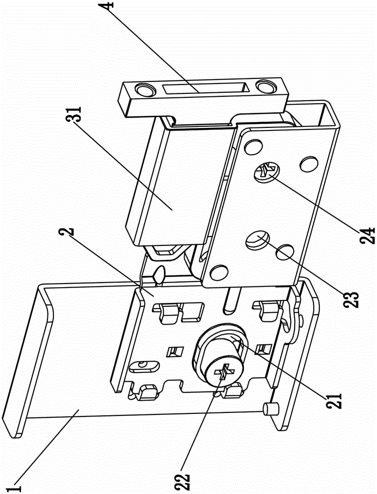
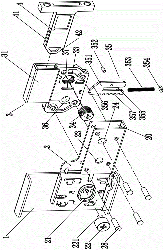
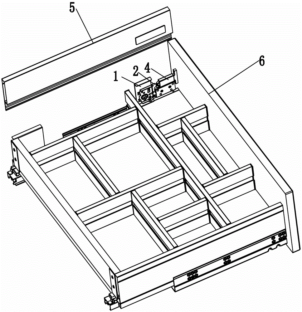
[0023] Embodiment one, see Figure 1 to Figure 4 As shown, a connection structure between a drawer side panel and a panel, including a fixed plate 1, a first movable seat 2, a second movable seat 3 and a panel connector 4, the first movable seat 2 is movable up and down on the fixed plate 1, The second movable seat 3 is movably arranged on the first movable seat 2 left and right, and the second movable seat 3 is provided with a screw hole 33, an unlocking hole 36, a dead bolt accommodating chamber 38, a sleeve 31 and a locking mechanism 35, and a locking mechanism 35 Including a compression spring 353 and a lock tongue 351, the first end of the lock tongue accommodation cavity 38 is provided with an opening 381, the second end of the lock tongue accommodation cavity 38 communicates with the inner cavity of the sleeve 31, and the unlocking hole 36 is located in the lock tongue accommodation. Next to the cavity 38, and the inner wall of the unlocking hole 36 communicates with th...
PUM
 Abstract
Description
Claims
Application Information