Power line fault indicator with time synchronization function

A fault indicator, time synchronization technology, applied in wired transmission systems, distribution line transmission systems, electrical components, etc., can solve the problems of inaccuracy, asynchronous data of each phase, asynchronous data of electric energy meters, etc., to achieve accurate records , Increase power consumption, data based on accurate effect

Active Publication Date: 2016-06-29
NINGBO JIANAN ELECTRONICS
View PDF3 Cites 3 Cited by
  • Summary
  • Abstract
  • Description
  • Claims
  • Application Information

AI Technical Summary

Problems solved by technology

The indicator unit collects data according to its own time, because each indicator unit is not synchronized, and the collected data of the three phases A, B, and C are not synchronized. Although these data can also be used to analyze grounding and short-circuit faults, they are not accurate enough. The data cannot be used as measurement monitoring
For example, electricity theft behavior monitoring can be compared with the load of each phase on the primary side and the load on the secondary side. The fault indicator can collect the load on the primary side, but because the data of each phase is not synchronized, it is also not synchronized with the data of the energy meter, so it cannot be done. Compared

Method used


Image

  • Power line fault indicator with time synchronization function

Examples


Embodiment Construction

[0015] The present invention will be described in further detail below in conjunction with the accompanying drawings and specific embodiments.

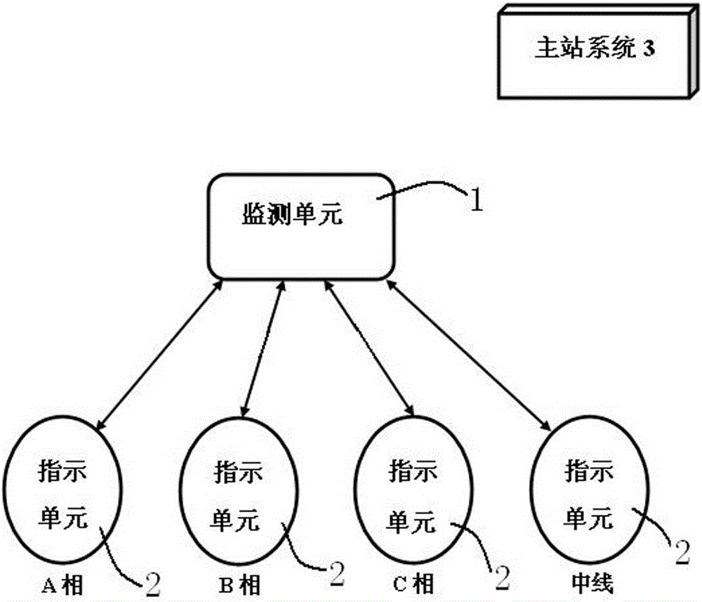
[0016] The power line fault indicator with time synchronization function includes an indication unit 2 and a monitoring unit 1. The monitoring unit 1 has a clock circuit. The main working process of the power line fault indicator is as follows:

[0017] 1) Instructing unit 2 collects load data in real time, conducts grounding or short-circuit fault analysis, and immediately executes the flop indication action after finding a grounding or short-circuit fault, and transmits the fault alarm information to monitoring unit 1 at the same time.

[0018] 2) The instruction unit 2 transmits the load data to the monitoring unit 1 periodically (once every 15 minutes).

[0019] 3) The monitoring unit 1 communicates with the master station system 3 through communication methods such as GPRS / 3G / 4G / FDDI. The master station system 3 can send a data ...


PUM


Abstract

The invention discloses a power line fault indicator with a time synchronization function. The power line fault indicator comprises indicating units and a monitoring unit, wherein the monitoring unit is provided with a clock circuit; the indicating units are provided with real-time clock registers; the indicating units transmit acquisition time of measured data or an alarm event to the monitoring unit; the monitoring unit transmits data including current time of the monitoring unit back to the indicating units; the indicating units calculate information transmission time after reception of the data; and the transmission time plus the current time received from the monitoring unit makes current time of the indicating units in order to realize time synchronization between the indicating units and the monitoring unit. Through adoption of the power line fault indicator, data and alarm information of the indicating units and the monitoring unit of the fault indicator is synchronized; a data basis of fault judgement becomes more accurate; and a record of a fault occurrence moment becomes more accurate.

Description

technical field [0001] The present invention relates to a power line fault indicator. Background technique [0002] The power line fault indicator originated in Germany in the 1980s. It was invented to indicate the path of the short-circuit current of the power line and help people find the fault point. Since the 1990s, my country has introduced and learned the development technology of foreign short-circuit indicators. [0003] In the 21st century, people began to pay attention to the problem of remote signal transmission of short circuit indicators. After the short-circuit indicator acts, it first gives a local indication, and then sends an action signal through a high-voltage insulating medium such as wireless or optical fiber. The realization of signal remote transmission breaks through the sight barriers of overhead lines and cable equipment, prolongs people's observation distance, and gradually evolves into a distribution line fault location system. It is combined w...

Claims


Application Information

Patent Timeline
Patent Type & Authority Applications(China)
IPC IPC(8): H04L12/24H04B3/54
CPCH04B3/542H04L41/064H04L41/0677
Inventor 龙翔林张军强刘秀峰马益平
Owner NINGBO JIANAN ELECTRONICS
Why Eureka
Try Eureka